I did some search online. Everything I saw was using existing FTDI232 breakout board to build stuff. This gives me the impression that the chip, when properly connected to USB and arduino, will need no programming and just works on a board.
I found this in its spec sheet:
Entire USB protocol handled on the chip. No USB specific firmware programming required.
I'm designing a project and decided to go from ATMEGA32U4 (after learning building bootloader) to ATMEGA328P-AU. I just need the FTDI chip like an old arduino would need it. I suppose a couple of decoupling caps and a cap between its DTR and ATMEGA328P-AU RESET will do. Am I too naive?
raschemmel:
So you're still in the dezign phase and want to know what hardware you need to load sketches to yiur 328 with an FTDI breakoutor a discrete SMD chip ?
Thanks for trying to understand what I was doing. I want to place ft232r on my board to load sketch. I want confirmation that the Ft232r chip can be placed on my board without itself requiring to be programmed first.
I don't have a YES or NO answer to your question. I'm a hardware person but I assume you know about installing the FTDI USB driver before using such a device : (see page 2 of datasheet)
The FT232 devices I've used have always worked without programming. I switched some time ago to the FT230 for the lower cost and smaller size. An early version of the FT230 was erroneously released in D2XX mode and had to be reprogrammed for VCP.
Common practice these days adds a clamp diode on the Atmega's reset pin to catch negative spikes caused by the cap. Remember to add a pullup resistor on the Atmega's reset pin, too.
Just want to add that you should buy from reputable sources. A few friends have been burned by counterfeits from ebay.
It works out of the box, you probably have to load a driver (I can't remember now) but that's all. And follow the current hardware designs of which there are 1000s.
Thanks everyone! I will look into the diode on reset. I didn't know that. Do you mean the 100nF cap I wil add between DTR and reset creates negative voltage?
I also used DTR to reset the MCU. My setup may be a bit complicated, but I think it gives significant understanding. I considered using the 3V3 from the driver (RS485) chip directly. However, after going through the capacitor (C7 on my schematic) that would only take RESET down to 1V7 which is not bellow the 0V9 threshold needed. So I have to level translate DTR to 5V which can then drive RESET down to almost ground potential through the capacitor. I could have a problem with some boards (e.g. Zero), except with IOREF used on the pull up resistor I should be fine without a diode. Schematic: http://epccs.org/indexes/Board/RPUadpt/Documents/RPUadpt,Schematic.pdf
Ok now I see... so that diode does look like a good idea.
Looking at my circuit... U4D is an open collector which will pull down fast, but the R14 will pull up slow which reduces the overshoot some (but how much I need to check). Unfortunately, the FTDI will pull to 5V fast and coupled through the capacitor make a 10V overshoot on the reset line. Page 291 of the ATmega328 datasheet shows that 12V will put it in Parallel Programming mode, and then things get messy. I had not considered all risk with this reset trick, I even show the overshoot on my schematic.
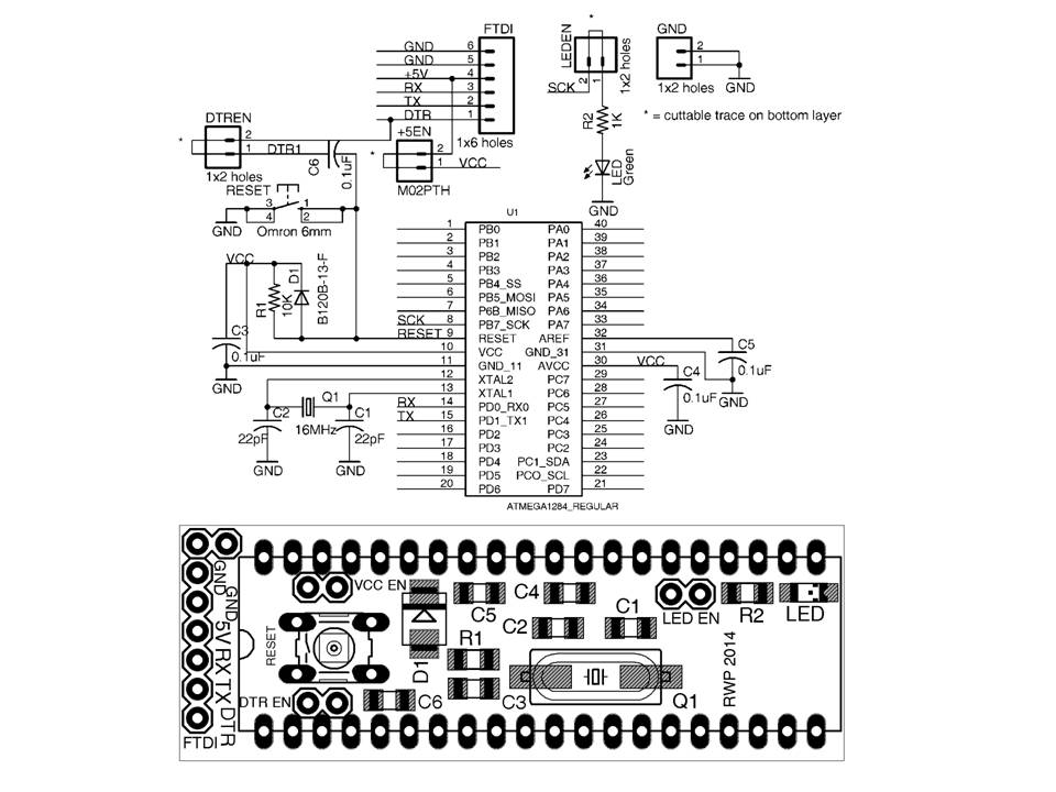
You can see that on my simple 1284P schematic - an FTDI Basic plugs on the FTDI header to supply the DTR and serial signals. I stopped mounting FT232 on my boards as a way to keep costs down and to make assembly easier - the FT232 TSSOP and QFRL packages have pins that are too close for hand assembly for us.
Thanks CR. Yes, the pins are really close. I've never soldered pins that close. Gotta learn how to drag solder. With the price of FTDI breakout boards so cheap, I've thought about just using them. Thing is, I want to make my device independent from ebay market trends
We tried 10 times, could only make 5 work, got 5 boards we could not salvage for FTDI. Even tried sending the cards out. Designs made to use FTDI modules since then. Price of chip plus connector plus cap & other parts is about a wash vs a module plus the parts don't need mounting. Can supply boards less a module also to lower cost as an option.
FT232, CP2102, PL2303, 16U2/8U2, or something, lots of ways to a USB/Serial interface.
My board area is also limited to free version of EAGLE. I'm making something open source. Gotta stay on the free version side of things so others can easily use and modify. I'll run out of board edge space for connectors if I use a breakout board.
So my experience with SMD is the SOIC (0.05" pitch) and the TQFP (0.8mm or 0.031" pitch). SOIC was no problem. TQFP was difficult for me. Did 3 only and struggled with a few pins. I'm going to learn drag soldering before trying the SSOP(0.025" or 0.635mm). I've been soldering with an iron.