Hi all,
sorry in advance it's my first post here...
Do we know a bit more about how the bq24195 has been used in this board?
Is the I2C monitoring (Host mode) implemented in some library? It seems like the pins are connected.
Also where do I find more info about analogRead(ADC_BATTERY) implementation?
I would like to write some code where one of the info is the battery charge status and level.
I have seen the MKR Zero Read Battery Voltage - Hackster.io
But I don't understand a couple of points, the LiPO charging level should 4.4V which is more than 3.3V and even with the resistor voltage divider is 3.45V when charging...
I cannot answer your first part but the second part is a little easier.
Most LiPo's are capable of topping out and giving a max of 4.7 volts.
This is above the normally acceptable level for most 3.3 volt boards.
Nominal is 3.3 Volts it seems they have restricted the absolute voltage to avoid damage or other related issues if I read the schematic properly.
There is also the drop across the voltage regulator to take into account when charging from the 5 volt USB connection.
4.7 volt does seem high but have had a couple (not on Arduino's) go as high as that.
Depreciates quickly to a more stable voltage of around 4.4 at switch on which is consistent with OP's findings.
Thanks guys for your inputs... still not quite what I need.
I'm aware of how LiPo charging works...
In fact I believe the way the TI chip used on the MKR board is implemented, run the charging @4.4V.
My interest is more into the monitoring part....
So, PB09 is a dedicated ADC port for the ADC_BATTERY conversion, that's clear.
Two things are not clear to me...
what is the VREF (3.3V, something else?) this ADC_Battery conversion is using?
The math doesn't add up...
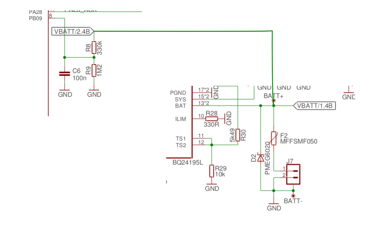
If VBAT=4.4V when charging with the voltage divider I will have on PB09 = 4.4 * (1200/(1200+330)) = 3.451 V (if remember ohm's law...lol) !!!! So, unless I'm missing something this is not correct... (schematic, my 4.4V assumption from TI data sheet).
Anyone form Arduino team, maybe can chip in...
So back to my question... Can someone shed some light on this? I made a quick image to make this a bit more clear for people not used to schematics.
With some digging into the the TI data sheet, it seems like the chip has been used in autonomous mode.
This makes the VBAT = 4.208V, that converted with the resistor net is a perfect 3.3V
Still would like to have bit more docs about the I2C implementation if any.
Thanks, and I hope this is useful info. I will work on some simple code and post it here later on. Just got a a new LiPO battery in the mail today
I was doing some digging into the way this operates on on the MKR 1010 wifi, and came across this thread, which is not totally the same as my question but it looks like the commenters here will know the answer.
The BQ24195L includes boost converter capability and is wired up in such a way that it should be able to generate 5V (at 1A?) at the 5V pin. Is this chip configured to do this? Curious as I'm working on a shield board and need to know if 5V is available when on battery. No, I don't actually have a battery yet to just test this with, and in any case if the answer is "no" then maybe it can be enabled as the chip is on the I2C bus and could be reconfigured. My limited understanding of the datasheet suggests maybe this just gets enabled when the OTG is plugged into something.
arielnh56:
The BQ24195L includes boost converter capability and is wired up in such a way that it should be able to generate 5V (at 1A?) at the 5V pin. Is this chip configured to do this?
The short answer is no. (that's what my scope confirmed). The 5V pin will report 3.3V when on battery.
The switching circuit (SW out) is boosting up to 3.8V to be rectified to 3.3V for the board Voltage supply lines (there are 2 of this).
You can get the 5V only when on USB or external VDC (controlled by Q2).
It seems like the the USB monitoring function (D+ and D-) of the TI BQ chip is also not implemented.
Scanning the I2C bus, my board reports:
I2C device found at address 0x60 ! >>> This should be the WiFi chip
I2C device found at address 0x6B ! >>> This should be the TI chip
Which means that the chip it is interfaced but I don't know at what level they have implemented it.
I don't know I2C programming too well but I'm learning, so if someone with a bit more knowledge want to chip in and suggest some code they're welcome. Maybe Arduino team can give us more info too.
Thanks for that answer. I'm working on a multiport I2C shield and this confirms that I need to give users the option to run ports at 5V or 3V3 depending on the application.
Smile6905:
The short answer is no. (that's what my scope confirmed). The 5V pin will report 3.3V when on battery.
The switching circuit (SW out) is boosting up to 3.8V to be rectified to 3.3V for the board Voltage supply lines (there are 2 of this).
You can get the 5V only when on USB or external VDC (controlled by Q2).
The long answer is yes. If you look at the datasheet of the BQ24195L you can find in section 8.3.1.5 that you can enable a boost to 5.1 volts on the PMID port. This is done by setting the OTG pin to high. This pin is connected to PA18 of the SAMD21 via Q3 (see arduino MKR wifi schematic). If you pull PA18 low this will activate OTG functionality and the 5.1V boost (If bus voltage is low enough, which it should be since you are running on battery only). This is connected to the 5V node through D3, a PMEG6020. So something ~5V should be available then.
An easy way to test this is by connecting a USB OTG device to your Arduino and confirming it is powered. Or just short the OTG pin to ground.
I've been looking into this myself and it seemed that OTG was the key (as well as setting REG01[5:4] to 10 via I2C, but that might already be the case).
I'm not very au fait with the workings of the Arduino but if someone could tell me if I'm on the right lines here I'd be very grateful:
How I can detect if USB power is being applied to know when to switch this on?
Should I just write 0x2B when I detect no USB (and try the above code again), 0x1B when I detect USB again?
disable_battery_fet looks important, can anyone help me with what it does? [[from docs: When battery is not attached, the BATFET should be turned off by setting REG07[5] to 1 to disable charging and
supplement mode.]]
The OTG pin alone is not enough, that's why my initial answer was not possible, you need to set I2C register on the BQ chip.
As you correctly pointed out the data sheet specify:
"USB current limit selection pin during buck mode, and active high enable pin during boost mode.
In buck mode with USB host, when OTG = High, IIN limit = 500 mA and when OTG = Low, IIN limit = 100 mA. The boost mode is activated when the REG01[5:4] = 10 and OTG pin is High."
I can help you test if you have further ideas.
Cheers,
Ermanno
ghvisser:
The long answer is yes. If you look at the datasheet.....
Of course I read the data sheet, you probably didn't.
The long answer is still NO, unless you set the register in BQ chip it will not work.
"The boost mode is activated when the REG01[5:4] = 10 and OTG pin is High."
arielnh56:
Thanks for that answer. I'm working on a multiport I2C shield and this confirms that I need to give users the option to run ports at 5V or 3V3 depending on the application.
Smile6905:
ghvisser
Of course I read the data sheet, you probably didn't.
The long answer is still NO, unless you set the register in BQ chip it will not work.
"The boost mode is activated when the REG01[5:4] = 10 and OTG pin is High."
...which is a case of just writing something over I2C. So how is the answer no? Am I missing something - forgive me for saying but it sounds like you're being quite rude to this guy?
Update - I've done some experimentation and found that reading REG08 can indicate whether or not USB 5v is connected. It's basically just the PG_STAT (Power Good) flag - if it's 1, USB +5V is present. If it's 0, we're just running on batteries. That's via:
Wire.beginTransmission(PMIC_ADDRESS);
Wire.write(PMIC_REG01);
Wire.write(B00101011); // see http://www.ti.com/lit/ds/symlink/bq24195l.pdf p28 - don't reset, normal watchdog, 10=OTG mode,1011 = 3.5V min sys voltage
Wire.endTransmission();
kierenj:
...which is a case of just writing something over I2C. So how is the answer no? Am I missing something - forgive me for saying but it sounds like you're being quite rude to this guy?
I didn't meant to be rude but he also did seem polite to me.... anyway...
No, you didn't miss my point which in fact was the beginning of the thread.
I was looking myself for ways to control the BQ chip for battery monitoring. Do you think can be done?
Smile6905:
I didn't meant to be rude but he also did seem polite to me.... anyway...
No, you didn't miss my point which in fact was the beginning of the thread.
I was looking myself for ways to control the BQ chip for battery monitoring. Do you think can be done?
Ah.
For that all I can see is:
Reading REG08 via getPowerState above tells you if it's not charging (00), initial charge (01), fast charge (10) or charge complete (11) in bits 4 and 5
Reading ADC_BATTERY gives you the battery voltage
I2C seems to work for reading (e.g. that state register) .. it feels like I've just got some problem writing.
Did you check this... You probably did, just to make sure..
" When the charger is in default mode, REG09[7] is HIGH. When the charger is in host mode, REG09[7] is LOW. After power-on-reset, the device starts in watchdog timer expiration state, or default mode. All the registers are in the default settings.
Any write command to bq24195L, bq24195 transitions the device from default mode to host mode. All the device parameters can be programmed by the host. To keep the device in host mode, the host has to reset the watchdog timer by writing 1 twice to REG01[6] before the watchdog timer expires (REG05[5:4]), or disable watchdog timer by setting REG05[5:4] = 00."