I'm working on my own take of an automatic fish feeder for my aquarium. Most of it is pretty straight forward (for me). LEDs, a piezo, RTC, etc.
However, I'm going to be using 3 stepper motors (28-BYJ48 with ULN2003 stepper module) and a 5V DC vibration motor from a broken video game controller. Other specs on the DC motor are unknown to me as it has no numbers on it anywhere other than "5V DC".
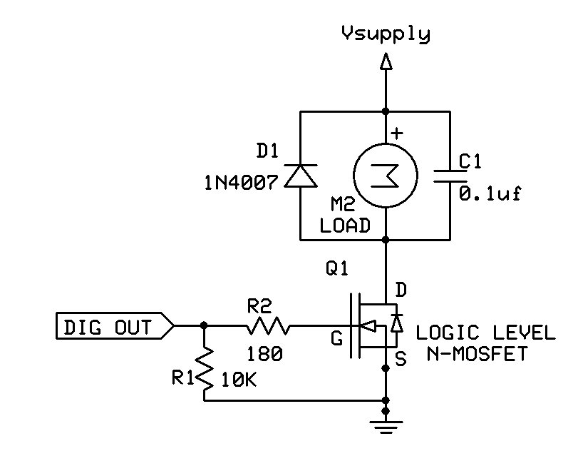
These will be powered via a 5V regulator (EDIT: buck converter, not regulator) that will be fed by a 12V 3A wall-wart. At no time will any 2 or more motors be running.
Thus, to save pin space, all three stepper modules will share the same 4 digital pins. I'll be using FQP30N06L mosfets to switch each module and the vibration motor on/off as each one is needed. I thought about using 2N2222A transistors. But from further reading, it seems to me a mosfet is better suited for the task. I know the FQP30N06L is overkill. But I have about 20 on hand not being used.
I'm thinking that covers most of the needed information. If not, just ask. Below is a diagram of how I "think" this should be wired up. I'm open to suggestions if something is completely wrong. Also, at this time, I'm not sure which diodes would be best. So, any and all advice is welcomed.
PS. The circles labeled "5V STEPPER" should be the stepper modules. And I'm thinking they shouldn't need a diode?
DangerToMyself:
These will be powered via a 5V regulator that will be fed by a 12V 3A wall-wart.
So almost 60% (7/12) of the power used by the circuit will be dissipated as heat in that regulator.
Wouldn't it be easier to use a 5volt (cellphone/tablet) supply?
Leo..
Thanks jremington. I missed that important detail in my research. I will make that change, pronto.
Hi Leo. I didn't find it relevant and did not mention that eventually I plan to add a 12v water pump for an automatic top off system. So, in lieu of that, a 5v charger would be the way to go.
I, also, used the term "5V regulator". And I should have said buck converter. Big difference. My apologies.
Thank you. High vs low side was not something I put any thought into. I'll look into it deeper. I'm under the impression that N channel mosfets aren't necessarily the best choice for high side. So, I may need to rethink my component choices.
I'm making the assumption that you're hinting to the voltage drop caused by the mosfet. If that's the case, couldn't I adjust the buck converter to a higher voltage to compensate? I know you had no way of knowing that detail. Again, didn't realize that tidbit would be relevant. But it's supposed to be adjustable up to 7 or so volts.
Since you are asking for a critique, if you gave me that schematic I would probably throw it away and
make my own that shows the stepper motor coils as a schematic coil symbol, label all the coils with the
correct phase and label all the gate signals with the corresponding phase name. In addition, if you look at the link you posted for those motors, you can clearly see that each coil has a center tap that is the power
(this looks like a 6-lead unipolar)
However, nowhere in this thread do I call it a schematic. It's a diagram that I drew up on my steering wheel. And drawn in a way that I easily understand. In my early learning stage of electronics, I don't "see" everything as a symbol.
Reading through this again, it occurs to me that my statement, as written, could be misconstrued as being resentful or disrespectful. I assure you it's not meant that way.
If I do another thread similar to this, I will see what I can do with an actual schematic.
However, nowhere in this thread do I call it a schematic. It's a diagram that I drew up on my steering wheel. And drawn in a way that I easily understand. In my early learning stage of electronics, I don't "see" everything as a symbol.
Why would you ask a forum of experts with tens of years of experience if you did not want to learn the PROPER way to draw it ?
Don't take this the wrong way but we really don't care why you drew it the way you did.
You presented an illustration and your post title was "Critique my mosfet diagram" and that's what I did.
You can give a million excuses for drawing a diagram wrong and it wouldn't matter.
Asking us to critique is in fact just another way of saying "Is this the CORRECT way to draw this ?"
I think I answered your question. I don't know if you were really interested in the correct way but there it is.
Take it or leave it.