I learned about Bitlash and that is perfect to test the motor setup (Arduino, L293D controller, motor, power).
Quite some time I tried to get ESP8266-01 in addition or as replacement onto MTS as well allowing wireless interactive control of speed and direction. I had to give up because of motor voltage spikes resetting the Wifi chip, see thread HOW TO SECURE ESP8266-01 FROM MOTOR VOLTAGE SPIKES? -- although it was really nice to wirelessly telnet through ESP8266-01 into Bitlash running on Arduino(!).
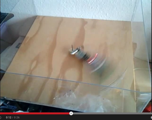
Today I completed first real Arduino controlled run (youtube link):
5V Arduino powered by 3.7V LiPo fully loaded with 4.16V
Program loops PWM from 80 to 160 in single steps with a delay of 50ms, then it waits for 10 seconds at 160 and then stops the motor (while entering blink LED mode).
The whole wooden arm with mounted stuff does weigh 75g.
You can hear at end of video that the wheel is bumping and therefore has no 100% ground contact.
I think you are testing the wheel as much as the motor!
I decided on the (slowflyer) wheels when I was targeting the whole Arduino robot to be less than 30g in weight, including two motors. If going with the 3 times more torque one (18g per motor vs. 8g vs. 3g) perhaps different wheels would be better ... that is what I want to use MTS for, test first and build "asurano" then (Arduino Nano robot similar to Asuro).
Do you measure the motor current?
Not yet. Do you mean with analogRead() and store until motor stopped?
(I have given up on Wifi connect)
How?
Here is the technical data for the current 12V motor I test, text is German but you should get the information:
Before increasing PWM above 160 I eliminated last remaining mini breadboard (-12g) and replaced it equivalently by soldering solution (+1g) resulting in 52g total weight.
12 rounds in 3.16s is 3.80rps or 227rpm, with 1.33m per round for the wheel this is 5.05m/s or 18.18km/h(!).
And this is not my fastest motor, and runs at only PWM=160, there is still room to PWM=255 ...
So I have reached my target of 5m/s with ease and will now try to find out how much faster is possible. The real robot will have 2 motors which I would suspect will increase max speed also.
[5m/s because speed of 3.1m/s on average(!) seems to be state of the art currently, initial run of this video ]
(animated gif created with gifsicle at original speed)
Hi,
Would it improve things if you moved the pcb etc on the arm back towards to pivot point and beyond to give you some balance in the spinning axis.
I'm not up on the dim years of my physics 101 , but concentrating the load around the pivot point should reduce the angular momentum as well.
Hi,
For speed measurement, put an LED on the arm as far out as possible, pointing down.
A photo-transistor in the test bed can detect the passing LED and using another arduino, calculate RPM and hence motor shaft speed and arm tip speed.
The LED tip is good, I did plan to build a light barrier for rpm counting myself.
Unfortunately I have killed one of my photo resistors and cannot find the other ...
On load at pivot point -- I did what you proposed:
I depened the 3 LiPos for the 12V and put everything besides the motor to pivot point.
It was really good that I took a video!
Thank you so much Tom -- pivot point mass concentration gave 20% max speed boost !
Added a small wooden piece with superglue onto the moving wooden arm in order to prevent Arduino and LiPos moving away from pivot point.
I killed 2 Arduino Nanos by loose cables and 12V getting in contact with what it should not -- good that I had 3 Nanos (OK, have several Pro Minis that can be used as well). You can see small on/off switch below the Arduino that allows to live safely without removing cables for powering on/off.
The pivot point Tip from Tom gave another 4km/h max. speed! (youtube video)
11 rounds in 2.12s gives 5.19rps or 311.3rpm.
And wheel with 1.33m per round runs 6.90m/s or 24.84km/h!
If your motor has a spec and you have a reasonable idea of the load torque, it will give you
the right numbers within the tolerance you'd expect. Sizing motors is not rocket science
really! Its finding the datasheet for a small motor that's the trickiest part.
You have a good testbed there for a smooth flat surface, but usually its the lumps, bumps
and slopes that place the most demands on the drivetrain - check you have the torque
and power needed for the worse incline too.
I provided link to (12V) motor specification above, but here is a better photo:
Spannung: voltage
Leerlauf: running idle
Strom: current
Maximaler Wirkungsgrad: maximal degree of efficiency
Drehzahl: number of revolutions
Stromaufnahme: current consumption
Drehmomemnt: torque
Abgabeleistung: output power
Effizienz: efficiency
Calculating with 17.500 rpm gives:
π0.04817500 = 2638.9 m/min
What I have measured is:
6.90*60 = 414.0 m/min
So what to do with above motor specification?
Well I'd first calculate the velocity and force at the wheel rim, getting
v = 42 m/s, F =0.03N
Hmm, 0.03N is not enough force for anything really (3gf)! Clearly some gearing
is needed (which of course it always is with a small motor as torque is limited
by motor volume)
So,
How to proceed?
Work out the worst case torque (at the wheel) needed for inclines, acceleration that you need.
Work out the max speed (at the wheel).
the product of those two gives the power you need for the motor, but you'll
need to add 50 to 100% to allow for transmission losses if you use gears/belts.
with the gearing and wheel radius you can then map that to motor specifications,
and thereby select an appropriate motor.
Lets say I have 200g load I want to drive up a 1-in-10 incline worst case - thats
0.2N at the wheel (weight force x 0.1). With two motors you share that, so
0.1N per wheel. Want max speed of 5m/s, then power needed is 0.5W per motor
(double for good measure as will use gears, 1W motors).
Say a 20mm radius wheel, so torque = 2mNm, angular velocity 250 rad/s (2500rpm).
You motor can only do 0.7mNm, so lets assume 5:1 reduction gearing, gives it
3.5mNm and a angular velocity of 350rad/s.
Its rare that you can avoid reduction gearing of some form in a small motor - your
system is overloading your motor completely I think, so the motor can't get
close to its max speed - you are likely overloading the windings as it struggles to
supply enough torque.
If you want to get that rig going faster you need to reduce the friction at the pivot and try to reduce the air resistance. Remember that the force that moved things to the outside is also acting on the pivot and increasing the friction there.
If you don't believe the motor specs and want to test the motor you need to make a dynamometer.
If the point is to move a robot, the puny 0.00071Nm rating is not going to go away by
testing it (neither will making a low friction test rig remove friction from the actual
robot), you need to do the math and add the reduction gearing!
Thanks Mark for the detailed calculations, I will follow up on that later.
Thanks Russel on the friction, that will go away with two motors/wheels and give a little boost then.
You mentioned to consider the requirements, those are easy (at least for my first use case "line follower").
The surface is completely flat in simple scenario (screenshot from first 3.1m/s average video):
And I am very satisfied with the speeds achieved sofar, pretty sure that they cannot be reached because of all the turns. The last MTS run I did with this 12V motor was to take into account that the robot will have two motors/wheels sharing the load. So I moved the load into the middle of the wooden arm:
It was clear that this will reduce speed, but it did not that much (youtube video):
6.90m/s -> 5.46m/s or 24.84km/h -> 19.64km/h
Now regarding the total weight of the robot, I target for sub 70g (if using this motor) and not 200g:
After much good testing with 12V motor I started testing the 15V motor today.
After killing my 3rd and last Arduino Nano had to modify the soldering to work with Arduino Pro Mini. Interestingly the Arduino Pro Mini does not work with 4.18V from LiPo -- the Nano did even work fine with 3.9V.
For the motor now 4 LiPos give 16V, and a new connector in the middle gives 8V for Raw input of Arduino Pro Mini.
After getting very bumpy run with the wheel already used for the 15V motor I decided to enlarge the diameter of the wheel hole that worked so well before with 12V motor. Result is the same bumpy runs.
Next I tried to add weight to counter the bumps (the disconnected battery pack on the middle of the wooden arm), without success. The slowflyer wheels cannot be used with this motor.
Wheel bumping starts at 13s and is maximal at 17s.
Now have to wait for new wheels for the 12V motor and find alternate wheels for the 15V motor.
Today got new wheels with 64mm diameter (compared to 48mm before).
This is the middle diameter wheel of these three wheels -- 85mm will be sent when available again
I thought the wheel hole was a perfect fit for 12V motor axis -- it was not
LiPos were not fully loaded, only 11.23V compared to >12V.
2nd High speed accident with new 64mm diameter wheel.
Thought that wheel was a perfect fit for motor axis
Wheel got lost at 0:23, wheel hole was too wide for the speed/force.
Rowvid.com frame by frame analysis with new wheel diameter:
Just before accident 6 rounds in 1.4s gives 4.3rps or 257.1rpm.
Wheel moves 1.33m per round giving 5.7m/s or 20.52km/h.
Its good to see that like NASA and Spacex, you video your successes and failures, to learn from them.
A mean looking line follower, do they have a 1/4mile dragstip event at RobotChallenge?