Hello
I have built an IR LED to photo-diode object (a coin) detector, it uses an op-amp to amplify the signal and connects to analog 0 on the Arduino. Its for a box that puts on a light show when a coin is pushed through the slot.Here is the circuit diagram:
The NE5532P op-amp was the only 5v one I had in the bits box.
Below is the code on the Arduino, it shows a voltage of around 4.08v, and when a coin goes past a drop to 3.40v. While this works it only detects a coin that's moving relatively slowly, one that's freely dropping past is not picked up by the Arduino. I can see a negative pulse on the oscilloscope, obviously this pulse is not lasting long enough to be picked up in the loop which checks every 100 milliseconds. I don't want to reduce this as I'll also be having the Ardunio control lots of coloured LED's and a small TFT screen.
So, is there a small and compact way to pick up this short duration pulse, so I can have the Arduino check once every 300 or 400 milliseconds?
#define inPin0 0
unsigned long milliTime;
boolean coinOn = false;
void setup() {
  Serial.begin(9600);

}

void loop() {
  milliTime = millis();

  if (milliTime % 100 == 0 && coinOn == false) {
    // check for a coin
    int pinRead0 = analogRead(inPin0);
    float pVolt0 = pinRead0 / 1024.0 * 5.0;
    Serial.println(pVolt0);

    if (pVolt0 < 3.9) {
      coinOn = true;
    }
  }

  if (milliTime % 1000 == 0) {
    // do somthing once a second
    Serial.println("once a second");
  }

  if (coinOn == true) {
    // coin detected - do things
    Serial.println("***** coin *****");
    coinOn = false;
  }
  delay(1); // this stops everything being done twice per loop
}
Use an NE555 timer as a monostable and stretch the pulse that way.
Use the negative pulse to trigger an interrupt and have the interrupt service routine set a Boolean variable to true. Then in the loop look for the state of the variable and if it is true make it false and do your thing.
That is fraught, if you happen to miss the exact moment when it is evenly divisible by 1000. Better of saving the start time and looking for current time - start time >= 1000.
Your circuit seems odd - you haven't provided a bias current path to the +input of the
opamp.
But more importantly the NE5532 isn't 5V, it is designed for a minimum supply of 10V.
For instance +/-5V split supplies, so running it from +5 and ground won't work as you
think.
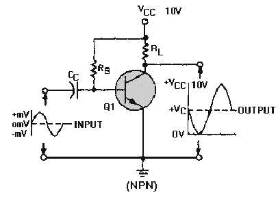
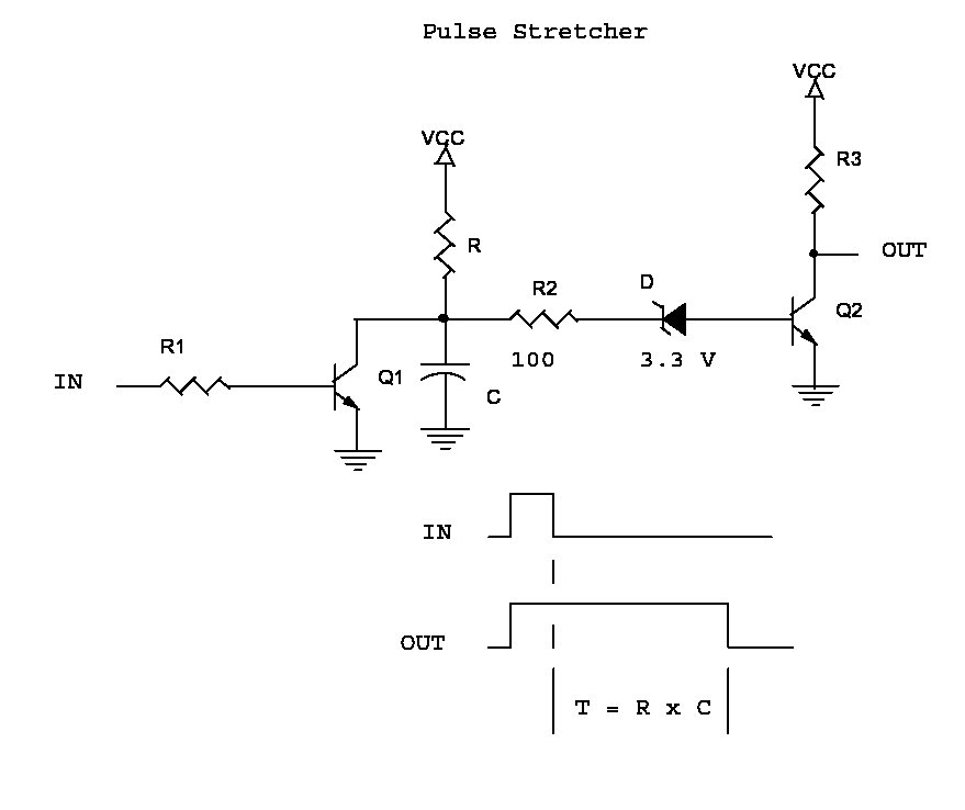
Another way might be to use a dalington transistor pair or 2 transistors biased to amplify the signal then feed it through a schmitt trigger to clean the waveform up .
Oh yes of course using a capacitor to "extend" your pulses ill design a circuit should be simple.
cjdelphi:
Another way might be to use a dalington transistor pair or 2 transistors biased to amplify the signal then feed it through a schmitt trigger to clean the waveform up .
cjdelphi:
Another way might be to use a dalington transistor pair or 2 transistors biased to amplify the signal then feed it through a schmitt trigger to clean the waveform up .
Sigh! - No it would not.
if biased properly so the sits off via the voltage divider, it will amplify the signal, why not? passed that 5v high (not low side of the transistor) to a not gate, or simply a buffer, and it will give a low and high edge or bypass it completey and design the schmitt trigger..
mike, point is you read what I say as literal, I do not mean Literal if i did i'd be listing components, they're just thoughts and yes it's possible to use just transistors to extend a pull... never made one, have you? so don't rule it out.
cjdelphi:
mike, point is you read what I say as literal, I do not mean Literal if i did i'd be listing components, they're just thoughts and yes it's possible to use just transistors to extend a pull... never made one, have you? so don't rule it out.
You ought to present your "concept" with a circuit sketch, not verbally.
I shall then.....I amplify the signal, clean it and extend the pulse, which gets fed into the IC... yup i'll have a think about it and design a circuit,
f biased properly so the sits off via the voltage divider, it will amplify the signal,
Yes it would, unfortunately this is not what the OP wanted.
mike, point is you read what I say as literal, I do not mean Literal if i did i'd be listing components, they're just thoughts and yes it's possible to use just transistors to extend a pull
I only have words to go off and your words as usual are rubbish and show a staggering ignorance of anything approaching electronic design. Maybe a schematic would show that either your words do not match your thoughts or your thoughts are wrong.
passed that 5v high (not low side of the transistor) to a not gate, or simply a buffer, and it will give a low and high edge or bypass it completey and design the schmitt trigger..
Yes I am taking these words to literally mean you are speaking in English, all the words are there, sadly they are jumbled up nonsense.
... never made one, have you?
Yes.
so don't rule it out.
Why not? As presented the idea you have will not extend the pulse which is what the OP wanted.
Of course according to your logic the OP is not to be taken literally so when he says he wants to extend a pulse then maybe he really wants to bake a cake and we should be telling him about that, but not in a literal sort of way.
Better to keep your mouth shut and be thought a fool as open it and remove all possible doubt - as someone famous once said.
I wonder Cjdelphi... If you have ANY IDEA of the photodiode current available in that circuit or the gain of the Op-Amp?.
Stretching the pulse is trivial.. A half monostable from a 40106 or a 4584 will serve nicely..
It is possible too, to use a 4069UB to do all of it with 3 sections connected as a linear amplifier 40 DB of gain can be easily realized and the remaining 3 sections can clean up and delay the pulse. The down side is that the 4069 isn't very fast because it is unbuffered..
I would suggest that in the future you supply schematics to back up your rather unusual? claims.
A photodiode is not what I would choose to use in this circuit. It takes a fair amount of gain after it, in a circuit a bit different than the one presented. There are problems with it, as pointed out by MarkT in post 5.
You could probably use a phototransistor without the use of an Op Amp. As long as the LED and phototransistor are well-shielded from outside light. With the proper amount of LED current, aiming correctly, and the proper selection of a collector resistor, you should be able to get less than 1V unblocked, and nearly 5V as the coin passes.
Take to heart everything up to and including post 5. As suggested, fix millitime now, you -will- run into a problem. It'll be intermittent at first, and again as suggested by then you may have forgotten.
Docedison:
I wonder Cjdelphi... If you have ANY IDEA of the photodiode current available in that circuit or the gain of the Op-Amp?.
Stretching the pulse is trivial.. A half monostable from a 40106 or a 4584 will serve nicely..
It is possible too, to use a 4069UB to do all of it with 3 sections connected as a linear amplifier 40 DB of gain can be easily realized and the remaining 3 sections can clean up and delay the pulse. The down side is that the 4069 isn't very fast because it is unbuffered..
I would suggest that in the future you supply schematics to back up your rather unusual? claims.
Doc
Amazing ignorance.
Saying this can't be done without using an ic ... and then like a pack of starving dogs attack me for suggesting otherwise lmao... i say wild more like an annoying poodle.
What you attached here is a lot different than what you posted about
cjdelphi:
Another way might be to use a dalington transistor pair or 2 transistors biased to amplify the signal then feed it through a schmitt trigger to clean the waveform up .
How is the "photodiode" supposed to interface with the AC amp you've attached?
I think that you ought to be able to explain your proposals beyond, "right, well here's a copy&paste of something or other; so make sure you get it all right, simple."
karl101 has left the building.
Moderator edit: Non-technical comment removed, (Nick Gammon)