I'm a beginner
I used a 16v 1000uf cap before a step down convertor witch was set to 5v to power my arduino using 5v pin and then my arduino wasn't able anymore to execute the code and also it won't appear on device manager anymore
I have a arduino nano clone and it worked before I did that
I also switched the power source from 9 to 12 and I think the arduino was plugged in this time
Which buck converter? How was everything wired up? If the converter really was generating a
clean 5V nothing bad would happen.
A little extra decoupling on the input to a DC-DC converter is not your problem, something else was
the issue - it sounds like a high voltage go to the 5V rail somehow.
MarkT:
Which buck converter? How was everything wired up? If the converter really was generating a
clean 5V nothing bad would happen.
A little extra decoupling on the input to a DC-DC converter is not your problem, something else was
the issue - it sounds like a high voltage go to the 5V rail somehow.
1.Variable power supply (weak old) set to 9v
2.The cap
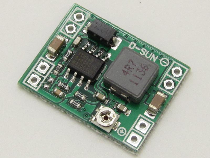
3.mp1584 step down set to 5v
4.arduino nano on 5v pin
+i/o expander
+lcd screen
Because I didn't modify much I suppose that the arduino died because of the cap
I read the voltage from the output of the convertor without the arduino and the voltage was slowly going from 5.2 to 4-3-2-1-0 (with multimeter) it is possibly that because of the low voltage on the regulated input the arduino killed it?
Maybe the capacitor was backwards... Or if you're sure you had the +end of the capacitor to the +voltage? Or maybe it was marked backwards or maybe it was defective.
Sometimes when you put a reverse voltage across a capacitor it doesn't die immediately... Sometimes the current slowly increases until the capacitor becomes a short circuit. Sometimes the cap will burn-up and sometimes the power supply will die.
In any case, a bad or reversed capacitor might kill the power supply but is shouldn't hurt the Arduino.
And this was an official Arduino or clone with a 16u2, not a clone with CH340G?
$5 says the '328p is still fine but the 16u2 is dead.
Man. I wish I had a box of 16u2 based arduinos that I didn't have to pay for that I could trash... the pieces of the puzzle are starting to fall into place for me w/regards to the mysteriously high failure rate of official boards' 16u2...
DrAzzy:
And this was an official Arduino or clone with a 16u2, not a clone with CH340G?
$5 says the '328p is still fine but the 16u2 is dead.
Man. I wish I had a box of 16u2 based arduinos that I didn't have to pay for that I could trash... the pieces of the puzzle are starting to fall into place for me w/regards to the mysteriously high failure rate of official boards' 16u2...
It Was a clone with ch340 but I think the USB cip is broken too because I got nothing on my computer when I plug it in, but the leds are going on an stay like this(rx)
The price was 3.4 usd
And I don't understand the rest of your post
Well, then that's not relevant... I got so excited. Somehow I thought you had a 16u2-based one, and those have a strangly large number of failures, usually when someone was doing something with the power rail while plugged into USB, and usually with the rest of board functionality intact, and I'd like to understand them so I can tell people who ask for help what they did. I can't think of another case where someone fried a ch340g on their Arduino board. I think you probably got power put onto it backwards or something.
Today i got the new nano, i upload arduino as isp on it, plug the other arduino to it, try to upload using programmer blink code and i got this error
Sketch uses 928 bytes (3%) of program storage space. Maximum is 30,720 bytes.
Global variables use 9 bytes (0%) of dynamic memory, leaving 2,039 bytes for local variables. Maximum is 2,048 bytes.
avrdude: Expected signature for ATmega328P is 1E 95 0F
         Double check chip, or use -F to override this check.
Wrong microcontroller found.  Did you select the right board from the Tools > Board menu?
after that, i tried to upload a blink code without the "using programmer" and it did upload it and both of them are blinking but if if plug only the broken one, it didn't work
also, i realised that the leds on the old one are lower brightness then the new one (not too much)
also, the old one is getting a little bit hotter then the new one
i suppose with that being said, there is no comeback for the old one, but i'm still afraid to plug the new one
i'm thinking that my variable step-down convertor was the prob or the power supply , shoud i build a circuit witch cut the voltage if exces 5.5v ?
Put Arduino as ISP back on the board and enable verbose upload, and try again and post output. With verbose upload, it will show you what it sees as the signature. If all 0's, it's wiring problem or bad/missing crystal when fuses say to use one. Otherwise, it points in other directions.
My questions right now are:
How i can use my arduino with the lcd and expander and also keep the lowest idle consumation
because it seems like the step down convertor isn't recomandated to be connected directly to the 5V pin
I also have a 5V regulator this mean i could increase the voltage to 7V and then plug the arduino via normal VIN and the other 2 components by my regulator but that will result in a bigger power consumtion and i don't need that
There must be a way of doing it better but i'm a beginner and this is the only thing that came up to my mind