Hi,
I've been working on a radio project for quite some time now. The project is almost finished, and as I wanted to reduce my dependency on components, I wanted to switch from using a MSGEQ7 to Arduino FHT (ArduinoFHT - Open Music Labs Wiki).
Unfortunately, I can't get it to work. My situation is a little bit different, and therefore I can't simply copy all solutions I could find.
The situtation:
- Barebone Atmega328 running on 3.3v / 8 Mhz
- Powered by LM317T from 12V
- 2 1.8" TFTs attached to SPI
- TEA5767 connected through I2C
- (TDA7375 on the board as well, works without problems)
- Custom made, high quality PCB
Problem:
The spectrum looks incorrect.
Wiring:
As my system is running on 3.3v, the analog pins are as well. I therefore reduce the max amplitude to 3.3v, and then apply a DC offset of 1.65v.
See attachment.
Remarks:
- There is a logarithmic potentiometer before the 'TEA5767 out or headphone' (see wiring).
- The spectrum 'height' increase when the potentiometer is in its last ~5-10%. So from 0% to about 90% the spectrum doesn't change in height, but 'vibrates' (1-2 blocks per row go on and off).
- The spectrum doesn't change when I disconnect the audio in.
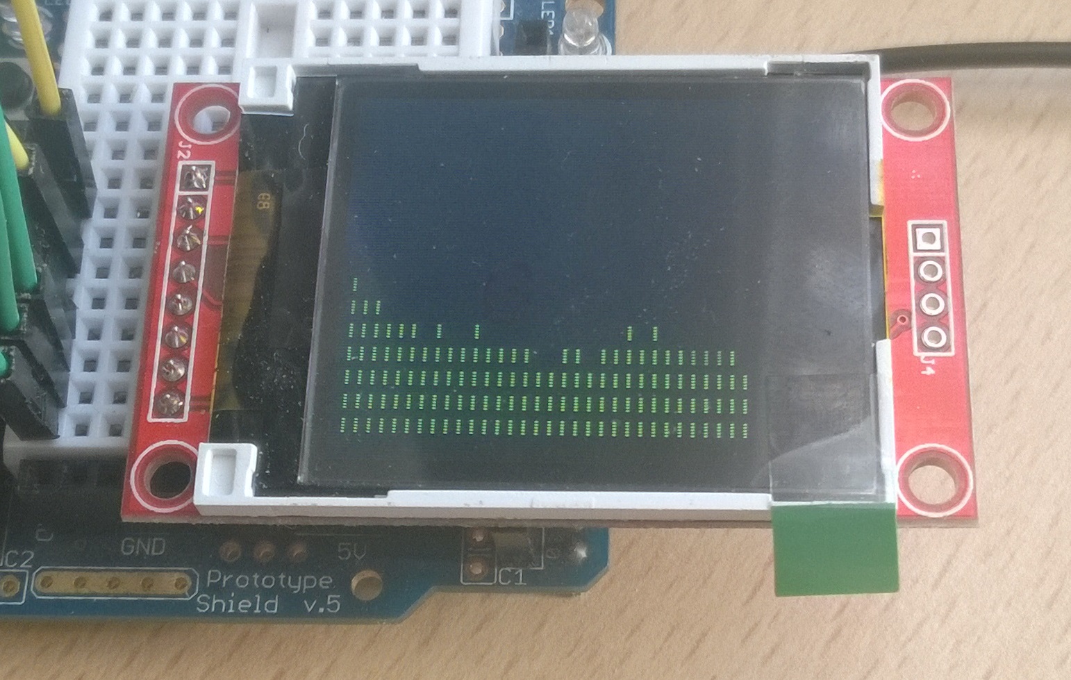
- I do receive some kind of signal, see attachment (those are the 32 bins of a FHT analysis with FHT_N = 32).
- Is the wiring correct? My electrical engineering skills are limited, but I can follow almost all explanations.
- Are the (time consuming) TFTs interfering with the FHT?
- The first display is almost never redrawn, the spectrum analyzer gets redrawn as often as possible.
I hope you can help me out, as although I've tried a lot of changes, I assume the solution is not so difficult.