Mega /w Sensor shield, 74HC595 & single 7-segment display --not working

Hi there.

I am trying to get a simple setup to work:

  • Arduino Mega with sensor shield
  • 74HC595 shift register
  • 7-segment display (ELS-43SURWA)

I connected the 7-segment display to the 74HC959 according to both datasheets:

I am using D10 as latch, D51 as Data-Pin, D52 as clock pin.

For testing purpose, i am using the following sketch:

int latchPin = 10; 
int dataPin = 51; 
int clockPin = 52; 

void setup() {
  pinMode(latchPin, OUTPUT);
  pinMode(dataPin, OUTPUT);
  pinMode(clockPin, OUTPUT);
}

void loop() {
  
  //0
  digitalWrite(latchPin, LOW);
  shiftOut(dataPin, clockPin, MSBFIRST, 64);
  digitalWrite(latchPin, HIGH);
  delay(1000);

  //1
  digitalWrite(latchPin, LOW);
  shiftOut(dataPin, clockPin, MSBFIRST, 121);
  digitalWrite(latchPin, HIGH);
  delay(1000);
  
  //2
  digitalWrite(latchPin, LOW);
  shiftOut(dataPin, clockPin, MSBFIRST, 36);
  digitalWrite(latchPin, HIGH);
  delay(1000);

  //3
  digitalWrite(latchPin, LOW);
  shiftOut(dataPin, clockPin, MSBFIRST, 48);
  digitalWrite(latchPin, HIGH);
  delay(1000);
  
  //4
  digitalWrite(latchPin, LOW);
  shiftOut(dataPin, clockPin, MSBFIRST, 25);
  digitalWrite(latchPin, HIGH);
  delay(1000);  
  
  //5
  digitalWrite(latchPin, LOW);
  shiftOut(dataPin, clockPin, MSBFIRST, 18);
  digitalWrite(latchPin, HIGH);
  delay(1000);

  //6
  digitalWrite(latchPin, LOW);
  shiftOut(dataPin, clockPin, MSBFIRST, 2);
  digitalWrite(latchPin, HIGH);
  delay(1000);

  //7
  digitalWrite(latchPin, LOW);
  shiftOut(dataPin, clockPin, MSBFIRST, 120);
  digitalWrite(latchPin, HIGH);
  delay(1000);

  //8
  digitalWrite(latchPin, LOW);
  shiftOut(dataPin, clockPin, MSBFIRST, 0);
  digitalWrite(latchPin, HIGH);
  delay(1000);

  //9
  digitalWrite(latchPin, LOW);
  shiftOut(dataPin, clockPin, MSBFIRST, 24);
  digitalWrite(latchPin, HIGH);
  delay(1000);
}

I have double- and triple-checked all connections, but the 7-segment is only showing weird characters. It is switching through the different "digits" though.

I am banging my head to the wall..just cant find my misstake...i also changed components to see if one was defect.

Any suggestions for troubleshooting?
It would help a lot to see a schematic of how the LED is wired to the 74595. Then we could equate the numbers in your shiftOut functions to segments ( A-G). For the common cathode display, write a 1 to light a segment, but, in your code, '0' has only 1 segment lit (64 = only bit 6 high), there should be only 1 segment unlit (G).

Cross post removed.

Pleaase use one thread per project that is more efficient for everybody reading it.

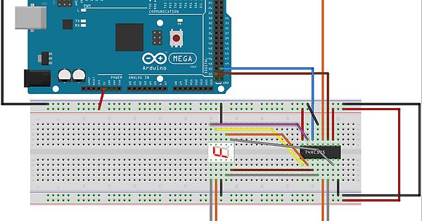
Here is an image of my wiring:

And please excuse the double-post, won't happen again. Promise.

groundFungus:
It would help a lot to see a schematic of how the LED is wired to the 74595. Then we could equate the numbers in your shiftOut functions to segments ( A-G). For the common cathode display, write a 1 to light a segment, but, in your code, '0' has only 1 segment lit (64 = only bit 6 high), there should be only 1 segment unlit (G).

You where right!

I changed the 64 to 191 and the 0 is getting displayed. Now the point is, that i am trying to use this with a program called "SimHub" to create a gear indicator for my racing simulators. They have preformated code, so i have to evaluate that code and see if i can change their values..

Up to work!

Thank you very much for pointing that out...one question though:

For common anode segments, this would have worked, right?

You have no current limiting resistors in the segments of you led, these are important for a long life of the chip / display.

For common anode segments, this would have worked, right?

Yes, you would write a '0' (LOW) to light a segment.

Grumpy_Mike:
You have no current limiting resistors in the segments of you led, these are important for a long life of the chip / display.

Would i use 1 for each segment in the connection between 74hc595 and the segments?
And how many ohms would you recommend?

10mA per segment should give enough brightness. To calculate the resistor value we use the formula
(supply voltage - led forward voltage) / led current = resistor value. The forward voltage is specified in the data sheet at 2.4V.
so the resistor would be (5V - 2.4V) / 10mA = 260 ohms. The closest standard value (5%) is 270 ohms.
If that is not bright enough calculate for a higher current (lower resistor). The absolute max current (specified in the data sheet) is 25mA.

Hi toni_latenz,

I've exactly the same issue as yours with SimHUB.
Wrong caracters are displayed on the 7 seg display, whereas I've no issue when I upload my own sketch into the arduino.

Have you been able to fix this issue?
Thanks a lot

Nams2590