I am using an Arduino MEGA, can I connect these to digital pins 38-44?
I tried doing so and when I followed the hello keypad tutorial, I couldn't enter any keys to show up in the serial monitor.
const byte ROWS = 4; //four rows
const byte COLS = 3; //three columns
char keys[ROWS][COLS] = {
{'1','2','3'},
{'4','5','6'},
{'7','8','9'},
{'*','0','#'},
};
byte rowPins[ROWS] = {43, 38, 39, 41};
//Can I use digital pins on Ard MEGA? I'd like to use Digital pins 38-44 since I have LCDs connected as well//
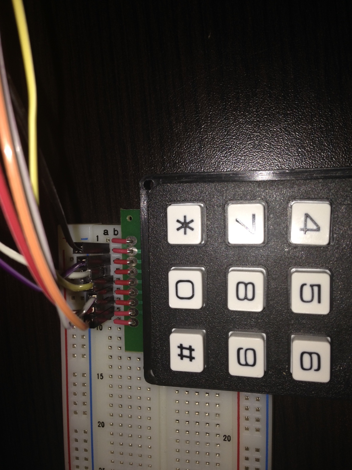
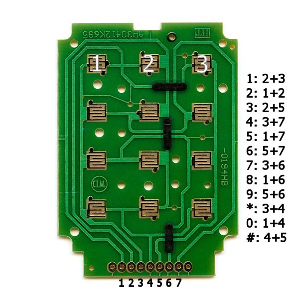
So using the products data sheet, I was able to get the correct wiring for the rows/columns.
However, although the key presses show up in the serial monitor, they stop appearing after a while.
Also, the red wires are touching the metal pin holes in the keypad, so there is a connection there without solder
If you don't want to solder wires directly to the pads, you could also use a female header. That way you can still "unplug" it when you're done and use it in another circuit later.
My goal is to use a code I'm currently tinkering with to accept user input from the keypad.:
// include the library code: #include <LiquidCrystal.h>
// initialize the library with the numbers of the interface pins
LiquidCrystal lcd(12, 11, 5, 4, 3, 2);
void setup() {
// set up the LCD's number of columns and rows:
lcd.begin(16, 2);
// Print a message to the LCD.
lcd.print("Select Part Family using Keypad:");
// set the cursor to column 0, line 1
// (note: line 1 is the second row, since counting begins with 0)
lcd.setCursor(0, 1);
lcd.print("1 = CFM // 2 = PRT-X // 3 = PRT-Y");
delay(750);
}
void loop() {
// scroll 13 positions (string length) to the left
// to move it offscreen left:
for (int positionCounter = 0; positionCounter < 13; positionCounter++) {
// scroll one position left:
lcd.scrollDisplayLeft();
// wait a bit:
delay(500);
}
// delay at the end of the full loop:
delay(0);
}
Once the user presses a number corresponding to a part, I'd like the program to ask for user confirmation.
Then, and only then, once the user presses a start push button, I'd like a servo I have to begin moving.
I have a servo code I've written, but I;m not sure how to get to that point.
Yes, I've seen that tutorial.
The issue is that I'm not familiar enough with the programming language to be able to code what I want to happen when a key is pressed.
Additionally, I am forgoing the keypad and using buttons on an LCD shield I have wired up.
However, I am unsure as to how to account for the analog pin for the 5 buttons on the shield.
I can't seem to find where to connect to on the shield, and once connected, how to code it into my program that the buttons will be utilized.
Are you saying you don't have the schematic or you don't understand the concepts of a voltage divider or an array ?
I can't seem to find where to connect to on the shield
This means what ? (you don't have the code which identifies the analog input pin or you don't have the schematic which shows the same thing ?
I'm really not understanding what the problem is here. Both the code and the schematic identify which analog input pin is used.
The first issue I had was that i could not physically locate the A0 pin on my LCD button shield, as I couldn't find a schematic of the pinout.
Trial and error brought me to the conclusion that the LCD shield A0 pin is the first pin in the J2 strip of pins.
My second question was: Did I need to account in my sketch the A0 on LCD to A0 on Arduino connection.
I did, in the form of the analogRead statement.
The shield A0 pin connects to the Arduino A0 through the header pin. The voltage on that pin is different for each button because they are connected at different points of the voltage divider and the code used an array that contains a value that falls in the midrange of the voltage for each button. Look at the LCD SHIELD example sketch.
You wouldn't be asking any of these questions if you had looked at the LinkSprite LCD SHIELD page
that has the code and schematic.
I had looked at the linksprite page numerous times.
As I said, the issue wasn;t the theory behind it, it was that I did not know which pin on the LCD button shield was A0.
I determined it was the first pin on the J2 strip through trial and error, that's all.
I found only the example code, although that only told me to use A0, which I knew already. i hadn;t known where it was physically.
In any case, I am able to get the keys (EDIT: LCD buttons) working with my current code, but am having trouble in creating a submenu system within a current menu system I have:
// Initialize the library with the numbers of the interface pins
LiquidCrystal lcd(12, 11, 5, 4, 3, 2);

//States for the menu.
int currentMenuItem = 0;
int lastState = 0;

void setup() {
   //Set the characters and column numbers.
   lcd.begin(16, 2);
   //Print default title.
   clearPrintTitle();
}

void loop() {
  //Call the main menu.
  mainMenu();
}

void mainMenu() {
  //State = 0 every loop cycle.
  int state = 0;
  //Refresh the button pressed.
  int x = analogRead (0);
  //Set the Row 0, Col 0 position.
  lcd.setCursor(0,0);

  //Check analog values from LCD Keypad Shield
  if (x < 100) {
    //Right
  } else if (x < 200) {
   //Up
    state = 1;
  } else if (x < 400){
   //Down
    state = 2;
  } else if (x < 600){
    //Left
  } else if (x < 800){
    //Select
    state = 3;
  }

  //If we are out of bounds on the menu, then reset it.
  if (currentMenuItem < 0 || currentMenuItem > 4) {
   currentMenuItem = 0;
  }

   //If we have changed Index, saves re-draws.
   if (state != lastState) {
      if (state == 1) {
         //If Up
          currentMenuItem = currentMenuItem - 1;
          displayMenu(currentMenuItem);
      } else if (state == 2) {
         //If Down
          currentMenuItem = currentMenuItem + 1;
          displayMenu(currentMenuItem);
      } else if (state == 3) {
         //If Selected
         selectMenu(currentMenuItem);
      }
      //Save the last State to compare.
      lastState = state;
   }
   //Small delay
  delay(5);
}

//Display Menu Option based on Index.
void displayMenu(int x) {
     switch (x) {
      case 1:
        clearPrintTitle();
        lcd.print ("-> CFM");
        break;
      case 2:
        clearPrintTitle();
        lcd.print ("-> FAM X");
        break;
       case 3:
        clearPrintTitle();
        lcd.print ("-> FAM Y");
        break;
      case 4:
        clearPrintTitle();
        lcd.print ("-> FAM Z");
        break;
    }
}

//Print a basic header on Row 1.
void clearPrintTitle() {
  lcd.clear();
  lcd.setCursor(0,0);
  lcd.print("Part Family?");
  lcd.setCursor(0,1);
}

//Show the selection on Screen.
void selectMenu(int x) {
   switch (x) {
      case 1:
        clearPrintTitle();
        lcd.print ("Selected CFM");
        //Call the function that belongs to Option 1
        break;
      case 2:
        clearPrintTitle();
        lcd.print ("Selected FAM X");
        //Call the function that belongs to Option 2
        break;
       case 3:
        clearPrintTitle();
        lcd.print ("Selected FAM Y");
        //Call the function that belongs to Option 3
        break;
      case 4:
        clearPrintTitle();
        lcd.print ("Selected FAM Z");
        //Call the function that belongs to Option 4
        break;
    }
}
In my code above, upon selecting a part family, it will display the selected family.
But my code implies I can call another function at this time as well.
Can I set a delay between the printing of "Selected _______" and that case creating a submenu for that part family?
In other words, once a part family is selected and printed to screen, a time delay occurs, and then the "parts in family" submenu appears.
The time delay I can do, but as for each case moving to it's own 'parts in family' submenu, this is where I am struggling.
I feel as if this can be achieved, but I am not sure how to go about it.