I just wanted to know if the diagram that I have is correct and not going to blow up anything. The motors that I am going to use will be either 6v or 12v. The external battery that I will be using is not a AA battery. It will either be a 2s or 3s lipo, if software that I was using did not have lipo (the 6v motor will use the 2s and the 12v will use the 3s). The resistors that I have are 10k. This is the MOSFET that I plan on using.
A couple of things what size diode do I need? is the mosfet needed for the single motor?
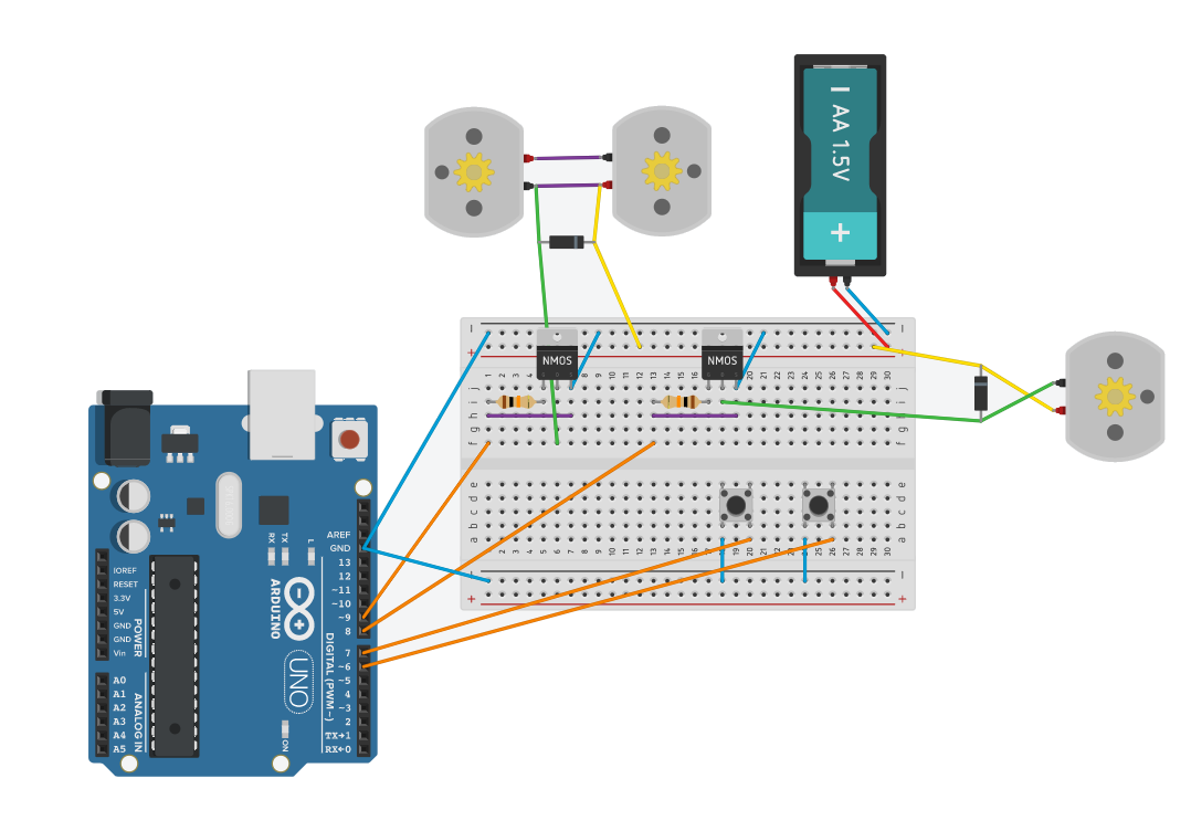
What the plan is, if you hold down one button the single motor will spin. If you hold down the second button the 2 motors will spin. The connections to each other for the double motors is meant to be that way.
Not in the diagram, I am also going to be putting a buck converter and setting it to 9v and attaching that to the lipo.
What you have won't do anything but burn up a couple I/O pins. D8 and D9 are tied to ground with the purple wires. Since the pins would be an output, and it's tied to ground, it's a short circuit. If you are not careful, you could do the same to D6 and 7.
Instead of the purple wire, substitute a 10k resistor to tie the gate to source/ground.
I thought that is what I did. I could not make the resistor smaller on this program so I have one end on the gate and the other to the source. I then have the source connected to the ground.
It looks like the two upper motors are connected so they will go in opposite directions, which is OK but you are applying power (green & yellow) across a wire. I'm guessing it is a drawing error but thought it should be mentioned.
BTW for any of my designs, I always connect the arduino outputs and inputs to the "protection" resistor first before any other connections. This is to be sure a misswire elsewhere will not toast the arduino.
Please go back to F**ing and switch to the "schematic view". It doesn't look as pretty but it's so much more readable. Spend a minute rearranging things to minimise the number of line-crossings and then post that picture.
It looks on the breadboard that you have purple wires shorting out the Arduino output pins to ground. Is this intentional?
As stated in #1, remove the purple wires. Adding the 10K (could be 50k) to ground makes sure the MosFet is off if the arduino is not connected, but is not required for functionality. But it is a good idea.
Regarding the series gate resistors and the motor diodes. The choices depend on whether or not you are PWM'ing the MosFet's and at what frequency.
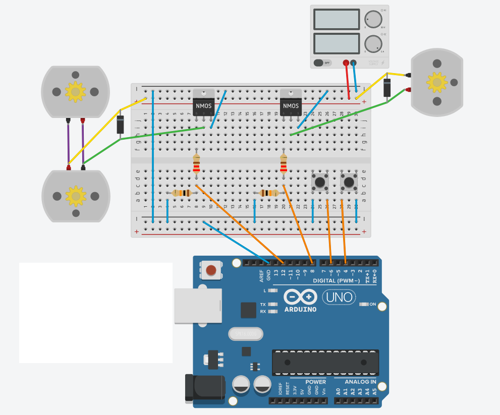
I removed the purple wire and added 2 more 10k resistors. I also moved the diagram around so that only 1 wire is crossing now.
I am using Tinkercad to create this and there is no schematic view for it.
I will not be PWM'ing the motors. The single motor will only run when the button is pushed. The double motors will run for a certain time when the other button is pushed and then shut off.
Still not right. You had the source wired to ground. That was correct. The issue was you had the gate wired to the source as well. That was wrong. That wire should have been changed to the 10k resistor.
What you have now is the source going through a 10k resistor tied to ground. The motor isn't going to run.
Just take your original drawing and replace the purple wires with the resistors.
I thought that is what I did in the first one I made. Because the resistors take up 4 points i could not have it span the mosfet from gate to source. That is why i had it go to the left. Was it because the purple wire was before the resistor?
In this one i did both motors in a different way. I think they do the same in the end.
The resistor in series with the gate should be ~220Ω to charge the mosfet input capacitance quickly.
Pin 9 - - - 220Ω - - - gate.
Also connect pin 9 to GND through a 10K resistor.
If the series resistor is too large, the mosfet will stay in the linear area too long and get hot, while not switch properly.
It could be me but I don't see the difference between #11 and #13, both are connected correctly.
Regarding the diodes, with no PWM nearly anything will work. The current rating should be at least what two motors will draw.
Regarding the 220 gate resistor. While the idea that lower resistance will switch the FET faster is absolutely correct. With your FET (very high current capability) and the motor (likely not too much current drawn) the gate resistor is not critical. I add this to give you a sense of the relative importance of different design decisions.
Just to mention the importance of good ground routing. Your design will work, however you will find as you progress into more demanding designs that how you run the grounds becomes more and more important. Once you get this going and are more familiar with the components, you might want to change the layout so the grounds are as nearly at one point as you can. In designs which require fast switching of moderate to high currents, lead length is your enemy.
You might also want to add some capacitance from + to - on your proto board. Perhaps a 10 to 50 µf and a 0.1 µf in parallel.
The main goal is to get this working first and then worry about the layout. Putting it on the board is one thing, but actually putting it in the project well will be a project in itself.
What this is for is for a nerf modification. The double motors will be the for the flywheels that will shoot out the darts. The single motor will be the pushing part. The double motors is where the problem could come into play. This is due if a dart jams into the motors and gets stuck and someone doesn't stop the motors.
I am trying to make the circuit as best that I can, without blowing up on someone. If something happens I can always fix it, but if i send this to someone, they might not be able to solder anything and the whole circuit is trash. So if the capacitance will only work for 1% of the blasters, then i will put that in. I am a programmer and I always program for that small chance, because out of all my years doing it, that 1% happens more then the people think.
The motors that I would be using is in this list Motor List
The MOSFET that i linked was the one that someone said was good. What I want to do is have something setup that I could almost put any motor in without changing any components. I was hoping that I could use 1n4007, due to their small size.
For wire sizing could i get away with 28 gauge for the everything expect for purple, yellow, green and the wires coming out of the power supply (those would be 16 or 18)?
For wire sizing could i get away with 28 gauge for the everything expect for purple, yellow, green and the wires coming out of the power supply (those would be 16 or 18)?
You should add the blue from the Mosfet Source to ground to the higher current list.
I think the #28 is fine, Unless you have very long runs you can likely drop the 16 /18 to a number 20 if you wish. Otherwise 16/18 would be fine.
The 1N400x is fine (x = any of the 1N4000 series will be OK here.)
It seems like the breadboard app i used to make this only has replay DPDT and SPDT. I did some googling and could only find big and expensive relay. It also returned switches as well. I don't think I was searching for the right stuff. I found a site that suggested to use a PMOSFET to help with the switching, but when reading the circuit i sort of got lost
In that diagram I am know 9v connects to the positive and assuming that the down pointing triangle is going to the ground. I do not know where the "BRAKE" and "ON" are connecting to.