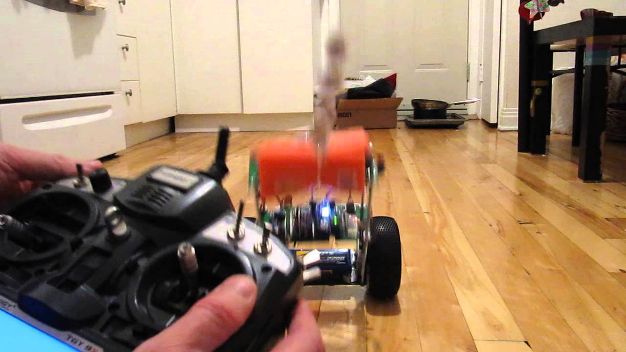
Balancing Robot Troubles

Hello all,
I too am building a self balancing robot like a lot of you members.

The hardware I'm running is:
Adafruit 10-DOF IMU (Adafruit 10-DOF IMU Breakout - L3GD20H + LSM303 + BMP180 : ID 1604 : $29.95 : Adafruit Industries, Unique & fun DIY electronics and kits)
Arduino Uno R3
Standard hobby geared motors
Adafruit motor driver shield v2.3 (https://www.adafruit.com/products/1438)

I'm reading the '.roll' field from the gyro and using that as an input for the bot.
Yes, I'm using only the gyro values for balancing (tried using the accelerometer, but the bot used to go haywire, even with the complimentary filter)
A little bit of help in this would also be great.

I'm using Brett Beauregard's PID library for the PID control.
My PID constants are:
Ki = 6.9
Kp = 4.3
Kd = 0.35

The bot balances well for small errors (<= 5deg), but after that it goes crazy, with sudden oscillations and jerks around.
One thing that I've noticed (in the serial monitor) is that when the motor start to correct the lean/tilt/error, after one or two cycles the motor gets a sudden large input (255 for the PWM pulse). I can't seem to get rid if that 'noise' in the output signal no matter what I do.

Right now I'm running the code at 100ms delay, as any other delay causes erratic behavior of the bot.

I'm attaching my code along with this post, and soon will upload a video showing the robot's behavior too.

Edit: The video is up on youtube: Balancing robot issues. - YouTube

Edit2, the code. Decided to post the code onto the post itself:

#include <Wire.h>
#include <PID_v1.h>
#include <Adafruit_10DOF.h>
#include <Adafruit_Sensor.h>
#include <Adafruit_LSM303_U.h>
#include <Adafruit_L3GD20_U.h>
#include <Adafruit_Simple_AHRS.h>
#include <Adafruit_MotorShield.h>

//Create sensor instances.
Adafruit_LSM303_Accel_Unified accel(30301);
Adafruit_LSM303_Mag_Unified   mag(30302);

//Create simple AHRS algorithm using the above sensors.
Adafruit_Simple_AHRS ahrs(&accel, &mag);
Adafruit_MotorShield AFMS = Adafruit_MotorShield();
Adafruit_DCMotor *myLeftMotor = AFMS.getMotor(1);
Adafruit_DCMotor *myRightMotor = AFMS.getMotor(2);

double Ki; //take analog input for manual setting of ki,kp,kd
double Kp;
double Kd;
//Define Variables we'll be connecting to
double Setpoint, Input, Output, Input1;
//Specify the links and initial tuning parameters
PID PID_A(&Input, &Output, &Setpoint, Kp, Ki, Kd, REVERSE);
int a = 100; //Set delay period in ms
void setup()
{
Serial.begin(115200);
//Initialize the sensors
accel.begin();
mag.begin();
AFMS.begin();//create with the default frequency 1.6KHz
 
//Set the speed to start, from 0 (off) to 255 (max speed)
myLeftMotor->setSpeed(0); myRightMotor->setSpeed(0);
myLeftMotor->run(FORWARD); myRightMotor->run(FORWARD);
//turn on motor
myLeftMotor->run(RELEASE); myRightMotor->run(RELEASE);
//initialize the variables we're linked to
Setpoint = -1.0;
PID_A.SetSampleTime(a);
PID_A.SetMode(AUTOMATIC);//turn the PID on
PID_A.SetOutputLimits(-255,255);
}

void loop(void)
{
 double K1 = 0.0;
 double K2 = 0.0;
 double K3 = 0.0;
 double Pot1 = A0;
 double Pot2 = A1;
 double Pot3 = A2;
 double Roll;
 double MotorSpeed;
 sensors_vec_t   orientation; 
boolean Res = (ahrs.getOrientation(&orientation));
Roll = orientation.roll;
/*sensors_event_t event; 
accel.getEvent(&event);
double Ay = event.acceleration.y;  
double Angle = 0.98*(Roll + Ay*0.01) + 0.02*Ay;*/
Input = Roll;  
K1 = analogRead(Pot1);
K2 = analogRead(Pot2);
K3 = analogRead(Pot3);
K1 = map(K1, 0, 1023, 0, 100);
K2 = map(K2, 0, 1023, 0, 100);
K3 = ((0.9*K3)/1023) + 0.09;
K1 = K1/10;
K2 = K2/10;
//K3 = K3/10;

Serial.print("Input: ");
Serial.print(Input);

Ki = K1;
Kp = K2;
Kd = K3;
PID_A.SetTunings(Ki, Kp, Kd);
PID_A.Compute();

Serial.print(" MotorSpeed: ");
Serial.println(Output);
Serial.print(" Ki ");
Serial.print(Ki);
Serial.print(" Kp ");
Serial.print(Kp);
Serial.print(" Kd ");
Serial.println(Kd);

if(Output < 0)
{ MotorSpeed = -Output;
  myLeftMotor->setSpeed(MotorSpeed);
  myLeftMotor->run(BACKWARD);
  myRightMotor->setSpeed(MotorSpeed);
  myRightMotor->run(BACKWARD);
/*Serial.print("MotorSpeed: ");
Serial.print(MotorSpeed);*/

  //delay(a);

}

else 
{ MotorSpeed = Output;
  myLeftMotor->setSpeed(MotorSpeed);
  myLeftMotor->run(FORWARD);
  myRightMotor->setSpeed(MotorSpeed);
  myRightMotor->run(FORWARD);
 // delay(a);
}

delay(a);
}

Balancing_Robot3.ino (2.75 KB)

You need a much shorter delay, 5ms or less is good, as fast as you get readings from the gyro
is best - any delay will make things less stable.

@MarkT: I did keep the delay at 10ms at one point of time, but the bot used to behave crazily 'nervous'; used to give extremely jerky movements.

Alternatively, can I use continuous rotation servos?
I also will be building a following mechanism in the robot, any pointers on that?

Abhishek_G:
@MarkT: I did keep the delay at 10ms at one point of time, but the bot used to behave crazily 'nervous'; used to give extremely jerky movements.

Alternatively, can I use continuous rotation servos?
I also will be building a following mechanism in the robot, any pointers on that?

Make sure you account for motor dead-zone, where voltages below a certain value won't make the motor move. That's why they add some finite voltage, which can be obtained by putting the bot on the ground (propped up by something), then use your software to see how much voltage is needed to make the wheel turn. Do this for each wheel. The voltage needed to move a wheel can then be used as a base-line voltage (or offset voltage).

Not sure what you mean by 'delay' .... do you mean sampling period? 100 msec sampling period (if you mean that) is too much. I agree....drop it back down to 5 to 10 msec.

And avoid things in the loop that could lead to hang-ups and delays.

It's possible that your Kd is way too low, and possible that your Ki is way too high.

Start by setting all parameters to zero. Then increase the Kp until your bot is reasonably responsive. But certainly don't over-do it.... ie don't make kp massively large. Then increase Kd a fair bit, until you get nice corrective action. Ki can then be increased..... but probably doesn't need to be too high at all. Just some relatively small amount of Ki might be ok.

It looks like you are close to getting your bot to work. I think you're close to getting it to work nicely.

This line looks suspect to me though .....

double Angle = 0.98*(Roll + Ay0.01) + 0.02Ay;

Maybe you need to check yourself. If you had set earlier a 'delay' which I assume to be 100 msec, then is it true that your line above should be ....

double Angle = 0.98*(Roll + Ay0.100) + 0.02Ay; ?

I realise that you have commented it out, and have used your own code to implement the complementary filter. But since you should really use a smaller sampling period, such as 10 msec, then it would be better to use the original line:

double Angle = 0.98*(Roll + Ay0.01) + 0.02Ay

HOWEVER, the first bracketed part (ie. Roll + Ay*0.010 ) is supposed be a predicted angle based on gyroscope measurements, such as:

(Roll + angular_velocity_gyro * 0.01) where the '0.01' is the 10msec sampling period.

While the other term, namely the 0.02Ay shouldn't contain the same variable (ie. Ay) as the first bracketed term. The 0.02Ay term should involve an angle measured by the two-axis accelerometer method, so should be something like 0.02*two_axis_accelerometer_angle.

Should try something like:

Angle = 0.80*(Roll + angular_velocity_gyro) + (1-0.80)*two_axis_accelerometer_angle

So, what I'm saying is, 'Ay' shouldn't be appearing two times in this equation:

double Angle = 0.98*(Roll + Ay0.01) + 0.02Ay

However, your own implementation looks suspect as well.... as I can't see any complementary action going on with this line:

K3 = ((0.9*K3)/1023) + 0.09;

..... unless I'm misinterpreting something.

Southpark:
Not sure what you mean by 'delay' .... do you mean sampling period? 100 msec sampling period (if you mean that) is too much. I agree....drop it back down to 5 to 10 msec.

Start by setting all parameters to zero. Then increase the Kp until your bot is reasonably responsive. But certainly don't over-do it.... ie don't make kp massively large. Then increase Kd a fair bit, until you get nice corrective action. Ki can then be increased..... but probably doesn't need to be too high at all. Just some relatively small amount of Ki might be ok.

It looks like you are close to getting your bot to work. I think you're close to getting it to work nicely.

This line looks suspect to me though .....

double Angle = 0.98*(Roll + Ay0.01) + 0.02Ay;

Maybe you need to check yourself. If you had set earlier a 'delay' which I assume to be 100 msec, then is it true that your line above should be ....

double Angle = 0.98*(Roll + Ay0.100) + 0.02Ay; ?

I realise that you have commented it out, and have used your own code to implement the complementary filter. But since you should really use a smaller sampling period, such as 10 msec, then it would be better to use the original line:

double Angle = 0.98*(Roll + Ay0.01) + 0.02Ay

HOWEVER, the first bracketed part (ie. Roll + Ay*0.010 ) is supposed be a predicted angle based on gyroscope measurements, such as:

(Roll + angular_velocity_gyro * 0.01) where the '0.01' is the 10msec sampling period.

While the other term, namely the 0.02Ay shouldn't contain the same variable (ie. Ay) as the first bracketed term. The 0.02Ay term should involve an angle measured by the two-axis accelerometer method, so should be something like 0.02*two_axis_accelerometer_angle.

Should try something like:

Angle = 0.80*(Roll + angular_velocity_gyro) + (1-0.80)*two_axis_accelerometer_angle

So, what I'm saying is, 'Ay' shouldn't be appearing two times in this equation:

double Angle = 0.98*(Roll + Ay0.01) + 0.02Ay

However, your own implementation looks suspect as well.... as I can't see any complementary action going on with this line:

K3 = ((0.9*K3)/1023) + 0.09;

..... unless I'm misinterpreting something.

@Southpark:
As you had suspected, the 'delay'(variable "a") was a universal time period for both the sample time AND the time delay. Which was the same for both (100ms). On your suggestion, I did change the time periods for both sampling time and delay (5ms, 10ms, 50ms) but the bot was behaving CRAZY. And by crazy I mean it was shaking like a man with parkinsons.

So right now the time periods are: 50ms time delay, 100ms sampling time.
Yes, I know the 100ms sampling time is crazy high, but if I keep it too low, then the bot shakes real bad. Probably signal noise, as I haven't used any signal filters(I'm coming to that too).

The line which you had suspected:

K3 = ((0.9*K3)/1023) + 0.09;

is a mapping calculation to map the values of Pot3(0, 1023) onto K3(0.00, 0.99) and ultimately Kd.

I haven't used any sort of signal filter as I could not work it out(like you saw in the other line, I had commented it out).
I did get you point though; the variable "Ay" is the acceleration in the Y-axis, which now I realized is an incorrect parameter(if I'm correct here?). I'm looking for the code for that, can't find much documentation for my IMU.

Right now, I'm going through the PID tuning steps that you suggested, and truly they're working like a charm! Thanks a lot for the same! :slight_smile:
Still working though, but I'll keep this post updated.

Abhishek_G:
Still working though, but I'll keep this post updated.

That's awesome Abhishek. Apologies for misinterpreting your Kd calculation. Excellent to hear that that you're getting new PID combinations that are making your bot behave better. Looks like your bot is really getting there. Nice!

Thanks Southpark!

So, I did try balancing the bot and tuning the PID constants. But sadly they didn't work.
The bot would be balanced for a bit, but then again it would start jerky/erratic motion.

Moreover, I've come to notice two more behavioral traits in the bot:

  1. Suddenly, the bot would go into crazy shakes. The serial monitor would show the motorspeed as 255(max value) for even small deviations. A closer look revealed that the input field aka the '.roll' field was getting spikes in the readings, where the value would go from 5 to as high as 50!

  2. The motors that I'm using are not moving in sync. I don't know how this could happen; as I've programmed both the motors to move at the same time. This causes the bot to move in a circle.

Also, now I'm getting skeptical at my choice of hardware.
Is the 10 DOF IMU good enough? Or should I buy an MPU 6050?
Is my motor driver a proper choice?

Abhishek_G:
Thanks Southpark!

So, I did try balancing the bot and tuning the PID constants. But sadly they didn't work.
The bot would be balanced for a bit, but then again it would start jerky/erratic motion.

Moreover, I've come to notice two more behavioral traits in the bot:

  1. Suddenly, the bot would go into crazy shakes. The serial monitor would show the motorspeed as 255(max value) for even small deviations. A closer look revealed that the input field aka the '.roll' field was getting spikes in the readings, where the value would go from 5 to as high as 50!

  2. The motors that I'm using are not moving in sync. I don't know how this could happen; as I've programmed both the motors to move at the same time. This causes the bot to move in a circle.

Also, now I'm getting skeptical at my choice of hardware.
Is the 10 DOF IMU good enough? Or should I buy an MPU 6050?
Is my motor driver a proper choice?

Hi again Abhishek,

At the moment, it really appears that your hardware is completely adequate for this balancing bot. The bot is truly trying to balance.

Your 10 DOF IMU should be fine. For my bot, I use a 6050, but I reckon your IMU should work too. But make sure that you run some test code - where the processor and IMU is active only, but with motors not active (turned off). Make sure that the IMU is at least giving sensible (more or less expected) readings.

I had a case where a MPU6050 had 'zero' readings for one of the axes, while other axes readings were fine. I replaced it with another MPU6050, and all readings were fine. Then double-checked by putting the original 6050 back in..... once again (no reading for that axis). The issue was a failed IMU. So - no wonder my bot wasn't behaving properly.

Another thing is - make sure that if you use any serial communications in your software, then set the rate to 115200. Don't set it to anything lower than that. Otherwise the laggyness will inhibit the desired control action.

Also - the software. Absolutely necessary to use a working control algorithm and code that is fully debugged (as in no errors in the software implementation).

It's important to know that at least two different methods for measuring the angle should be used. One is the very basic two-axis angle measurement which is nothing more than the arctan of a ratio of values from the accelerometer. And the other measurement of angle is from the gyroscope..... a very simple product of angular velocity reading and a change in time. If you google 'sainsmart bot', it will lead you to code that is probably used by a heap of people out there. Or, at least the algorithm within is used by heaps of people. I am using that particular kit, and the code really works excellently for my bot (but only after I change some offsets that applies to my particular bot characteristics ..... eg. it's weight, motor dead-zone etc).

The reason for using 2 different kinds of angle measurements is because the accelerometer method tends to give accurate readings when the bot isn't moving about too much, but not so good when the bot is moving about a lot. The gyroscope method can give accurate readings over relatively short durations in time. Therefore one of the most simple and effective ways to make use of both of the angle readings is to use a basic equation that involves adding weights to each reading.

Eg... processed_angle = 0.8*(oldangle + gyro_angular_velocity * change_in_time) + ( 1-0.8 )*two_axis_accelerometer_angle_measurement

The value of 'processed_angle' will eventually become 'oldangle' for the next loop iteration.

Now, getting back to readings from the IMU. It will certainly be beneficial to use something to hold up your bot in the 0 degrees position (ie. vertical). Then use your own software (with motors de-activated) to do say 1000 or 2000 measurements of the accelerometer and gyroscope values. Then use a spreadsheet or your own processing software to take an AVERAGE of EACH of the measurement values in your data. You can then use the averaged values as offsets (for calibrating your IMU). This will at least let you remove some error that an uncalibrated IMU may give out. For example, your bot may physically be sitting at a true angle of 0 degrees, but your two-axis (uncalibrated) angle measurement might be giving out -2 degree. This could mean that your bot will end up trying to lean at -2 degree (which puts the centre of mass away from the vertical axis)..... which could make things hard for your bot. So the best situation is - if your bot really has 0 degree lean, then the CALIBRATED angle measurements should hopefully give '0 degree'.

I think the most important things are:

  1. Find out what PWM values are needed to avoid dead-zone lags due to motor dead-zone. This just means having at least some mininum PWM power going to the motors at all times. To find out how much minimum PWM to apply will just require using your own testing software to drive each motor (while the bot is on the ground, and is supported by something to stop it from falling over).

If you are currently applying the same PWM signal to both wheels, then remember that while each motor is of the same model, one of them might have different dead-zone behaviour (maybe). Hence it can be beneficial to not output identical PWM signals to both motors. That's why many code will control each motor with their own PWM signal (taking motor offsets into account). Some code might have identical offsets, but it will be up to the programmer to decide on whether to use identical offsets or not. It may turn out through testing that the offsets should not be identical.

  1. calibrated IMU readings

  2. fully functional control algorithm implementing PID control and at least 'complementary filter' for achieving decent estimates of angle.

  3. Use adequate time resolution (small enough sampling period that can be handled properly by the processor). Eg. 1msec to 10msec sampling period.

  4. Minimise unnecessary bits of code that might slow down the looping algorithm in the code. Eg. unnecessary print statements etc.

  5. Be aware of 'backlash' in motors, where there's a gap where nothing happens a bit when transitioning from forward to reverse motion (and vice versa), due to gaps in gears. This presents a region of uncontrolled movement, and could make things tricky when it comes to locking onto a stable zero steady-state-error for angle.

  6. If the bot doesn't have wheel encoders for measuring ground-speed, then it's possible that the bot won't be able to maintain a perfectly balanced position for a relatively long time. There could be back and forth drifting every now and again. Although, using the bot on carpet can help with keeping the bot very still (in the vertical position).

Abhishek_G:
@MarkT: I did keep the delay at 10ms at one point of time, but the bot used to behave crazily 'nervous'; used to give extremely jerky movements.

Sounds like too much D term - that will produce more jitter and noise - although the quality
of the sensor data may also be a limiting factor. If there is a way to smooth any noise from
the differential (speed) signal it can help reduce noise from the D term.

There is also the issue of whether you use the angle or angular rate as the input to the PID,
or a combination of both - there is probably a whole range of hybrid strategies to explore. The
output could be direct to PWM or to control motor current (torque control) using a high speed
inner PID loop and motor current sensing.

Alternatively, can I use continuous rotation servos?
I also will be building a following mechanism in the robot, any pointers on that?

Any further control loops should drive the balance set-point to control acceleration and
therefore speed. I believe careful tuning is needed to avoid fighting the balance loop - slow
control inputs only.

Ahbishek, my commercially bought bot kit is sort of along the same lines as yours. Once you got the sensors working well, and sensor calibration done, plus sampling period at an adequate rate, I expect that your bot will be as good as many of them out there.

I made this video today - it's not equipped with it's own battery yet..... as it is still on it's way (from ebay). The bot kit itself is pretty good. The software needed a tiny bit of work though.

Hi Southpark,

Finally, the bot is completed! :smiley:
I'll post the video soon.

The main issue was that I was using ONLY the roll of the accelerometer, i.e. the angle measured by the two-axis measurement method. And add to that, I wasn't using the complimentary filter. So the bot was all jittery. The IMU was factory calibrated, so didn't have to work on that.

Apart from that, I went through making two frames - one of 18mm plywood(turned out too heavy; new motors were drawing too much current from the motordriver) and another from aluminum box sections(my current frame, lightweight and is a charm to work on). That's where I had to put in most of my time.

Although complete, the bot can only maintain its balance for small variations (~+-3deg). This has more to do with the torque/speed of the motors and right now it doesn't look that it can be solved immediately(new motors are 3 weeks away from delivery).

Yes, I saw your video and have a couple of questions:

  1. Is the IMU placed at the top? I've read at a lot of places that it should align with the wheel axis.

  2. What motors are you using? Mine are toy/hobby motors, so they have a bit of backlash; doesn't cause too much problems, but it isn't the smoothest bot too.

Apart from that, I'm thinking to add a light/IR following mechanism. Could you help me with that? I don't know anything of how to make this bot move around.

Lastly, thanks a ton for your help! @MarkT: I'm grateful to you as well!
Both of you guys helped me achieve more progress than I could in the past 6-8 months!!

Regards,
Abhi.

Hi Abhishek! Congratulations on getting your bot to balance, and for figuring out what needed to be done. Great effort actually.

You asked where the IMU was placed for my bot. With the one I have, the IMU is a MPU9150, and it's location is at the top of my bot.

The gyroscopes measure angular velocity, not acceleration, so theoretically doesn't matter whether they're at the top or the bottom. Accelerometers - on the other hand - are sensitive to acceleration - so the further they are from the base (pivot point), the larger the acceleration. But, at the moment, I'm using gyro angle measurements only - at least until I can get some averaging or filtering done on the accelerometer measurements, I'm using the gyro measurements for getting angles. My bot only operates for 5 to 10 minutes at a time, and using gyro angle is just fine.

For moving the bot around, one general method is via wireless remote control (eg. using a pair of nRF24L01 wireless transceiver boards - which are apparently based on a frequency shift keying communications method at 2.4 GHz frequency). The Arduino forums/github etc have excellent examples of making these work for you - very easily and very conveniently. So, remotely, you can drive the motors to move the bot around.

Okay.
Apart from using wireless, I also want to include/develop a user/object/light following mechanism.
Right now I've zeroed in on using an ultrasound sensor to maintain a constant distance from an object.

But before I do any of that, I don't know how to get the bot move about.
How do I push the balancing loop to make it move?

Okay, so I've gotten through with uploading the video (Balancing robot issues - 2 - YouTube).

As I'd said earlier, the motors have a little bit of backlash, and then to add to it they're underrated for the size/weight/torque of the frame. So precise balancing and holding a position is out the window for now.

But, apart from that, the bot does hold position for very small inclinations/error.
I'll probably have to retune the PID constants(they're hardcoded in the video).

Also, I'm thinking of using steppers to control the robot (These: http://www.explorelabs.com/stepper-motor-68-oz-in-400-steps-rev ).

This guy has done an AMAZING job with steppers:

Abhishek_G:
Okay, so I've gotten through with uploading the video (https://youtu.be/3kc1Kz-sm0Q).

Hi Abhi, your original bot was certainly zippy enough. I believe that your original bot was certainly capable of balancing really well. I don't just mean trying to balance..... but actually balancing extremely well. I believe it's just a matter of working on the software (control algorithm), plus PID settings, and making sure the sensors are giving decent/clean readings.

Steppers tend to draw a lot of current when the motors aren't turning much, and will likely drain battery quickly. Will still be interesting to see the results from the stepper motors though.

Southpark:
Hi Abhi, your original bot was certainly zippy enough. I believe that your original bot was certainly capable of balancing really well. I don't just mean trying to balance..... but actually balancing extremely well. I believe it's just a matter of working on the software (control algorithm), plus PID settings, and making sure the sensors are giving decent/clean readings.

Steppers tend to draw a lot of current when the motors aren't turning much, and will likely drain battery quickly. Will still be interesting to see the results from the stepper motors though.

Hi Southpark,
Agreed, the bot was zippy enough. but it couldn't hold its position(gear backlash) and also, as the gear ratios were high reduction, the final speed was low. So I decided to use a couple of steppers. I know, steppers will draw a lot of current, but at the moment I'm powering the bot with a laptop adapter.

That said, I have completed building the new bot(new bigger frame, new drivers, motors, bigger wheels). And glad to say, the newer bot runs amazingly! It holds position like there's no tomorrow.

I've used a couple of Pololu DRV8825 drivers to run two MotionKing NEMA17 steppers(1.3A per phase, 4-wire, bipolar) and the AccelStepper library (AccelStepper: AccelStepper library for Arduino) for controlling the motors.
The bot holds position wonderfully, like I said earlier. But the only issue I have is with motor speed. The UNO can give the steppers a max speed of 4000 steps/s due to its clock speed limiting the pulses. I'd require a Due now, for its higher clock speed(84MHz).

Apart from that, there's absolutely ZERO problems in the balancing part. :smiley:
Now, I'm working on adding a couple of ultrasound sensors, to make it a basic obstacle avoider or follower.

Here's the video of the bot in action: https://www.youtube.com/watch?v=cobwLFzAhv4

P. S. - Sorry for the delayed response, working on the new motor drivers took away a lot of time.

Hi abhi. Your bot is balancing excellently. I knew you'd get there. Congrats in getting it nice and stable. Looks great.

Southpark:
Hi abhi. Your bot is balancing excellently. I knew you'd get there. Congrats in getting it nice and stable. Looks great.

Thanks!
That's very kind:)
I'm working on the "follower" part, which should be completed by today(its 10.24am here). Will keep the thread updated and will soon post the video.