In case anyone needs help calibrating the LSM303DLHC board (triple-axis accelerometer+magnetometer) and is looking for a tilt compensated heading, this could help them.
I'm relative new to Arduino and don't have prior programming experience, so probably the code isn't the fastest nor the most elegant, but it seems to work fine.
Any comments and improvements are welcome.
Calibration Software
Download the latest Magneto version from here: https://sites.google.com/site/sailboatinstruments1/home
Unzip executable.
LSM303 Libraries
Download LSM303 Libraries from here: https://github.com/pololu/lsm303-arduino/archive/master.zip
Unzip in the Arduino libraries folder.
Magnetometer Calibration
Copy and upload following code:
#include <Wire.h>
#include <LSM303.h>
LSM303 compass;

void setup()
{
Serial.begin(9600);
Wire.begin();
compass.init();
compass.enableDefault();
Serial.println("Magnetometer Uncalibrated (Units in Nanotesla)");
}

void loop()
{
compass.read();
float Xm_print, Ym_print, Zm_print;

Xm_print = compass.m.x*(100000.0/1100.0); // Gain X [LSB/Gauss] for selected sensor input field range (1.3 in these case)
Ym_print = compass.m.y*(100000.0/1100.0) // Gain Y [LSB/Gauss] for selected sensor input field range
Zm_print = compass.m.z*(100000.0/980.0 );  // Gain Z [LSB/Gauss] for selected sensor input field range

Serial.print(Xm_print, 10); Serial.print(" "); Serial.print(Ym_print, 10); Serial.print(" "); Serial.println(Zm_print, 10);
delay(125);
}
Download LSM303DLHC datasheet: http://www.st.com/web/en/resource/technical/document/datasheet/DM00027543.pdf
In the LSM303.cpp file (https://github.com/pololu/lsm303-arduino/blob/master/LSM303/LSM303.cpp), the default value for the CRB_REG_M register is 0x20.
If you convert that hexadecimal value to binary, you get 00100000.
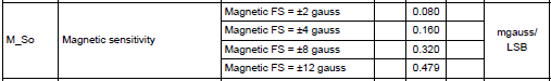
Checking table N°75 on page number 38 in the datasheet, you'll notice the default sensor input field range is +/- 1.3 gauss.
Adjust LSB/Gauss if necessary in the sketch.
Open serial monitor and move board for several minutes in all directions.
Copy values in a textfile (txt) and save file.
Execute Magneto.
Load textfile with raw readings.
For the norm of magnetic field, visit this page: NCEI Geomagnetic Calculators
Enter your location and calculate magnetic field.
Copy the value to Magneto (units are the same).
Click calibrate.
Copy and replace the combined bias values and combined scale factors in this sketchbook (check signs; by default, bias is substracted from raw values):
#include <Wire.h>
#include <LSM303.h>
LSM303 compass;

void setup()
{
Serial.begin(9600);
Wire.begin();
compass.init();
compass.enableDefault();
Serial.println("Magnetometer Calibrated (Units in Nanotesla)");
}

void loop()
{
compass.read();
float Xm_off, Ym_off, Zm_off, Xm_cal, Ym_cal, Zm_cal;

Xm_off = compass.m.x*(100000.0/1100.0) - 8397.862881; //X-axis combined bias (Non calibrated data - bias)
Ym_off = compass.m.y*(100000.0/1100.0) - 3307.507492; //Y-axis combined bias (Default: substracting bias)
Zm_off = compass.m.z*(100000.0/980.0 ) + 2718.831179; //Z-axis combined bias

Xm_cal =  0.949393*Xm_off + 0.006185*Ym_off + 0.015063*Zm_off; //X-axis correction for combined scale factors (Default: positive factors)
Ym_cal =  0.006185*Xm_off + 0.950124*Ym_off + 0.003084*Zm_off; //Y-axis correction for combined scale factors
Zm_cal =  0.015063*Xm_off + 0.003084*Ym_off + 0.880435*Zm_off; //Z-axis correction for combined scale factors

Serial.print(Xm_cal, 10); Serial.print(" "); Serial.print(Ym_cal, 10); Serial.print(" "); Serial.println(Zm_cal, 10);
delay(125);
}
Upload code, open serial monitor and move board in all directions.
Copy values in a textfile (txt) and save file.
Load in Magneto textfile with calibrated values.
Click calibrate.
Combined bias should now be closer to 0.
Accelerometer Calibration
Copy and upload following code:
#include <Wire.h>
#include <LSM303.h>
LSM303 compass;

void setup()
{
Serial.begin(9600);
Wire.begin();
compass.init();
compass.enableDefault();
Serial.println("Accelerometer Uncalibrated (Units in mGal)");
}

void loop()
{
compass.read();
float Xa_print, Ya_print, Za_print;

Xa_print = compass.a.x/16.0; //Acceleration data registers contain a left-aligned 12-bit number, so values should be shifted right by 4 bits (divided by 16)
Ya_print = compass.a.y/16.0;
Za_print = compass.a.z/16.0;

Serial.print(Xa_print); Serial.print(" "); Serial.print(Ya_print); Serial.print(" "); Serial.println(Za_print);
delay(125);
}
Open serial monitor and move board for several minutes along all axes.
Copy values in a textfile (txt) and save file.
Execute Magneto.
Load textfile with raw readings.
For the norm of gravitational field, enter 1000 (since raw units are in milli-Galileo).
In the LSM303.cpp file, the default value for the CTRL_REG4_A register is 0x08.
If you convert that hexadecimal value to binary, you get 00001000.
Checking table N°27 in the datasheet, you'll notice the accelerometer has a scale selection of +/- 2G.
And checking table N°3 for that scale selection, the linear acceleration sensitivity is 1 mg/LSB.
Click calibrate.
Copy the combined bias values and combined scale factors in this sketchbook:
#include <Wire.h>
#include <LSM303.h>
LSM303 compass;

void setup()
{
Serial.begin(9600);
Wire.begin();
compass.init();
compass.enableDefault();
Serial.println("Accelerometer Calibrated (Units in mGal)");
}

void loop()
{
compass.read();
float Xa_off, Ya_off, Za_off, Xa_cal, Ya_cal, Za_cal;

Xa_off = compass.a.x/16.0 + 6.008747; //X-axis combined bias (Non calibrated data - bias)
Ya_off = compass.a.y/16.0 - 18.648762; //Y-axis combined bias (Default: substracting bias)
Za_off = compass.a.z/16.0 + 10.808316; //Z-axis combined bias

Xa_cal =  0.980977*Xa_off + 0.001993*Ya_off - 0.004377*Za_off; //X-axis correction for combined scale factors (Default: positive factors)
Ya_cal =  0.001993*Xa_off + 0.998259*Ya_off - 0.000417*Za_off; //Y-axis correction for combined scale factors
Za_cal = -0.004377*Xa_off - 0.000417*Ya_off + 0.942771*Za_off; //Z-axis correction for combined scale factors

Serial.print(Xa_cal); Serial.print(" "); Serial.print(Ya_cal); Serial.print(" "); Serial.println(Za_cal);
delay(125);
}
Upload code, repeat procedure and check if bias decreased.
Pitch, Roll and Heading
Use following code for printing pitch, roll and tilt compensated heading (code includes low-pass filter, adjustable with the alpha value).
Replace calibration values.
#include <Wire.h>
#include <LSM303.h>

LSM303 compass;

const float alpha = 0.15;
float fXa = 0;
float fYa = 0;
float fZa = 0;
float fXm = 0;
float fYm = 0;
float fZm = 0;

void setup() {
Serial.begin(9600);
Wire.begin();
compass.init();
compass.enableDefault();
}

void loop()
{
compass.read();
float pitch, pitch_print, roll, roll_print, Heading, Xa_off, Ya_off, Za_off, Xa_cal, Ya_cal, Za_cal, Xm_off, Ym_off, Zm_off, Xm_cal, Ym_cal, Zm_cal, fXm_comp, fYm_comp;

// Accelerometer calibration
Xa_off = compass.a.x/16.0 + 6.008747;
Ya_off = compass.a.y/16.0 - 18.648762;
Za_off = compass.a.z/16.0 + 10.808316;
Xa_cal =  0.980977*Xa_off + 0.001993*Ya_off - 0.004377*Za_off;
Ya_cal =  0.001993*Xa_off + 0.998259*Ya_off - 0.000417*Za_off;
Za_cal = -0.004377*Xa_off - 0.000417*Ya_off + 0.942771*Za_off;

// Magnetometer calibration
Xm_off = compass.m.x*(100000.0/1100.0) - 8397.862881;
Ym_off = compass.m.y*(100000.0/1100.0) - 3307.507492;
Zm_off = compass.m.z*(100000.0/980.0 ) + 2718.831179;
Xm_cal =  0.949393*Xm_off + 0.006185*Ym_off + 0.015063*Zm_off;
Ym_cal =  0.006185*Xm_off + 0.950124*Ym_off + 0.003084*Zm_off;
Zm_cal =  0.015063*Xm_off + 0.003084*Ym_off + 0.880435*Zm_off;

// Low-Pass filter accelerometer
fXa = Xa_cal * alpha + (fXa * (1.0 - alpha));
fYa = Ya_cal * alpha + (fYa * (1.0 - alpha));
fZa = Za_cal * alpha + (fZa * (1.0 - alpha));

// Low-Pass filter magnetometer
fXm = Xm_cal * alpha + (fXm * (1.0 - alpha));
fYm = Ym_cal * alpha + (fYm * (1.0 - alpha));
fZm = Zm_cal * alpha + (fZm * (1.0 - alpha));

// Pitch and roll
roll  = atan2(fYa, sqrt(fXa*fXa + fZa*fZa));
pitch = atan2(fXa, sqrt(fYa*fYa + fZa*fZa));
roll_print = roll*180.0/M_PI;
pitch_print = pitch*180.0/M_PI;

// Tilt compensated magnetic sensor measurements
fXm_comp = fXm*cos(pitch)+fZm*sin(pitch);
fYm_comp = fXm*sin(roll)*sin(pitch)+fYm*cos(roll)-fZm*sin(roll)*cos(pitch);

// Arctangent of y/x
Heading = (atan2(fYm_comp,fXm_comp)*180.0)/M_PI;
if (Heading < 0)
Heading += 360;

Serial.print("Pitch (X): "); Serial.print(pitch_print); Serial.print("  ");
Serial.print("Roll (Y): "); Serial.print(roll_print); Serial.print("  ");
Serial.print("Heading: "); Serial.println(Heading);
delay(250);
}