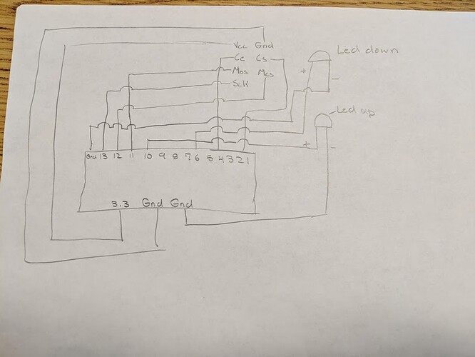
NRF24l01 LED Remote Modification not working

Hi,
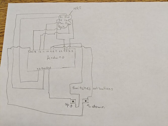
I'm creating a chicken coop door that will automatically open and close when it's night or day outside and alert me via the NF24l01 when the door is open or closed by lighting up an LED. I've successfully created a working prototype of that door opening part of the code. I am having some serious difficulty with the NF24l01! I have tried multiple examples from all corners of the internet. I have an Arduino UNO that will serve as the transmitter and another Arduino UNO that will serve as a receiver. I have 2 switches attached to the door. One that will switch on (go from 0 to 1) when the door is open and the other will switch on when the door is closed (also goes from 0 to 1). The Arduino would then send the door's state to the other Arduino. The other Arduino would then turn on an LED that is labeled as up when the door is up, and turn on another LED when the door is down. Unfortunately none of that works.
I've loaded the LED remote Example and that example doesn't send anything to the other Arduino. I tried the Getting Started example and that did work, I just don't understand how to modify it for my use.

Any help would be super appreciated!

I am using the
GitHub - nRF24/RF24: OSI Layer 2 driver for nRF24L01 on Arduino & Raspberry Pi/Linux Devices library.

Right now on the Arduino Uno attached to the door the pin layout is

CS-2
CE-4
MOS -11
MSC-12
SCK -13

For the switch it goes
Door up -8
Door down -9

And on the LED Arduino it's
CS-2
CE-4
MOS -11
MSC-12
SCK -13

The Transmitter Arduino's Code

#include <SPI.h>
#include "RF24.h"

boolean powerState  = LOW;

int photocell = 0;

int upDetect = 11;
int downDetect = 9;

int manualUp = 10;
int manualDown = 3;

int upswitchReading;
int downswitchReading;
int photocellReading;
int manualUpReading;
int manualDownReading;
int DATA;

RF24 radio(2, 4);
byte addresses[][6] = {"1Node", "2Node"};

void setup(void) {
  pinMode (upDetect, INPUT_PULLUP);
  pinMode (downDetect, INPUT_PULLUP);

  pinMode (manualDown, INPUT_PULLUP);
  pinMode (manualUp, INPUT_PULLUP);
  pinMode (6, OUTPUT);
  pinMode (5, OUTPUT);
  digitalWrite (5, HIGH);

  radio.begin();
  radio.setPALevel(RF24_PA_LOW);
  radio.openWritingPipe(addresses[1]);

  Serial.begin(9600);
  delay(100);
}

void loop(void) {
  Serial.println("Up Switch Reading = ");
  upswitchReading = digitalRead(upDetect);
  Serial.println(upswitchReading, DEC);
  delay(1000);

  Serial.println("Down Switch Reading = ");
  downswitchReading = digitalRead(downDetect);
  Serial.println(downswitchReading, DEC);
  delay(1000);

  Serial.println("Manual Down Switch = ");
  manualDownReading = digitalRead(manualDown);
  Serial.println(manualDownReading, DEC);
  delay(1000);

  Serial.println("Manual UP Switch = ");
  manualUpReading = digitalRead(manualUp);
  Serial.println(manualUpReading, DEC);
  delay(1000);

  Serial.println("  Photocell reading = ");
  photocellReading = analogRead(photocell);
  Serial.println(photocellReading);
  delay(1000);


  if (photocellReading < 400) {
    powerState = HIGH;
  }
  else if (photocellReading > 400) {
    powerState = LOW;
  }

  if (manualDownReading == 0) {
    powerState = HIGH;
  }

  else if (manualUpReading == 0) {
    powerState = LOW;
  }

  digitalWrite(6, powerState);

  if (downswitchReading == 1) {
    DATA == 100;
  }

  if (downswitchReading == 0 || upswitchReading == 0) {
    DATA == 250;
  }

  if (upswitchReading == 1) {
    DATA == 200;
  }
  radio.write( &DATA, sizeof(DATA ) );

  Serial.print("DATA = ");
  Serial.println(DATA);
}

The Receiver Arduino's Code

#include <SPI.h>
#include "RF24.h"

RF24 radio (2, 4);

byte addresses[][6] = {"1Node", "2Node"};
int dataReceived;
int UpLED = 10;
int DownLED = 6;

void setup() {
  pinMode(UpLED, OUTPUT);
  pinMode (DownLED, OUTPUT);

  radio.begin();
  radio.setPALevel(RF24_PA_MIN);
  //  myRadio.setPALevel(RF24_PA_MAX);

  radio.openReadingPipe(1, addresses[0]);
  radio.startListening();
  Serial.begin(115200);
  delay(1000);
}


void loop()
{

  if ( radio.available()) // Check for incoming data from transmitter
  {
    while (radio.available())  // While there is data ready
    {
      radio.read( &dataReceived, sizeof(dataReceived) ); // Get the data payload (You must have defined that already!)
    }

    if (dataReceived == 200) {
      digitalWrite(DownLED, HIGH);
    }
    if (dataReceived == 250) {
      digitalWrite(DownLED, LOW);
      digitalWrite(UpLED, LOW);
    }
    if (dataReceived == 100) {
      digitalWrite(UpLED, HIGH);
    }


    Serial.print("Data received = ");
    Serial.println(dataReceived);
  }

}
The Getting Started Example is

#include <SPI.h>
#include "RF24.h"

/****************** User Config ***************************/
/***      Set this radio as radio number 0 or 1         ***/
bool radioNumber = 0;

/* Hardware configuration: Set up nRF24L01 radio on SPI bus plus pins 7 & 8 */
RF24 radio(7,8);
/**********************************************************/

byte addresses[][6] = {"1Node","2Node"};

// Used to control whether this node is sending or receiving
bool role = 0;

void setup() {
  Serial.begin(115200);
  Serial.println(F("RF24/examples/GettingStarted"));
  Serial.println(F("*** PRESS 'T' to begin transmitting to the other node"));
  
  radio.begin();

  // Set the PA Level low to prevent power supply related issues since this is a
 // getting_started sketch, and the likelihood of close proximity of the devices. RF24_PA_MAX is default.
  radio.setPALevel(RF24_PA_LOW);
  
  // Open a writing and reading pipe on each radio, with opposite addresses
  if(radioNumber){
    radio.openWritingPipe(addresses[1]);
    radio.openReadingPipe(1,addresses[0]);
  }else{
    radio.openWritingPipe(addresses[0]);
    radio.openReadingPipe(1,addresses[1]);
  }
  
  // Start the radio listening for data
  radio.startListening();
}

void loop() {
  
  
/****************** Ping Out Role ***************************/  
if (role == 1)  {
    
    radio.stopListening();                                    // First, stop listening so we can talk.
    
    
    Serial.println(F("Now sending"));

    unsigned long start_time = micros();                             // Take the time, and send it.  This will block until complete
     if (!radio.write( &start_time, sizeof(unsigned long) )){
       Serial.println(F("failed"));
     }
        
    radio.startListening();                                    // Now, continue listening
    
    unsigned long started_waiting_at = micros();               // Set up a timeout period, get the current microseconds
    boolean timeout = false;                                   // Set up a variable to indicate if a response was received or not
    
    while ( ! radio.available() ){                             // While nothing is received
      if (micros() - started_waiting_at > 200000 ){            // If waited longer than 200ms, indicate timeout and exit while loop
          timeout = true;
          break;
      }      
    }
        
    if ( timeout ){                                             // Describe the results
        Serial.println(F("Failed, response timed out."));
    }else{
        unsigned long got_time;                                 // Grab the response, compare, and send to debugging spew
        radio.read( &got_time, sizeof(unsigned long) );
        unsigned long end_time = micros();
        
        // Spew it
        Serial.print(F("Sent "));
        Serial.print(start_time);
        Serial.print(F(", Got response "));
        Serial.print(got_time);
        Serial.print(F(", Round-trip delay "));
        Serial.print(end_time-start_time);
        Serial.println(F(" microseconds"));
    }

    // Try again 1s later
    delay(1000);
  }


/****************** Pong Back Role ***************************/

  if ( role == 0 )
  {
    unsigned long got_time;
    
    if( radio.available()){
                                                                    // Variable for the received timestamp
      while (radio.available()) {                                   // While there is data ready
        radio.read( &got_time, sizeof(unsigned long) );             // Get the payload
      }
     
      radio.stopListening();                                        // First, stop listening so we can talk   
      radio.write( &got_time, sizeof(unsigned long) );              // Send the final one back.      
      radio.startListening();                                       // Now, resume listening so we catch the next packets.     
      Serial.print(F("Sent response "));
      Serial.println(got_time);  
   }
 }


/****************** Change Roles via Serial Commands ***************************/

  if ( Serial.available() )
  {
    char c = toupper(Serial.read());
    if ( c == 'T' && role == 0 ){      
      Serial.println(F("*** CHANGING TO TRANSMIT ROLE -- PRESS 'R' TO SWITCH BACK"));
      role = 1;                  // Become the primary transmitter (ping out)
    
   }else
    if ( c == 'R' && role == 1 ){
      Serial.println(F("*** CHANGING TO RECEIVE ROLE -- PRESS 'T' TO SWITCH BACK"));      
       role = 0;                // Become the primary receiver (pong back)
       radio.startListening();
       
    }
  }


} // Loop

Hi,

I'm creating a chicken coop door that will automatically open and close when it's night or day outside and alert me via the NF24l01
when the door is open or closed by lighting up an LED.
I've successfully created a working prototype of that door opening part of the code.

I am having some serious difficulty with the NF24l01!
I have tried multiple examples from all corners of the internet. I have an Arduino UNO that will serve as the transmitter and another Arduino UNO that will serve as a receiver.

I have 2 switches attached to the door.
One that will switch on (go from 0 to 1) when the door is open
the other will switch on when the door is closed (also goes from 0 to 1).

The Arduino would then send the door's state to the other Arduino.

The other Arduino would then turn on an LED that is labeled as up when the door is up, and turn on another LED when the door is down.

Unfortunately none of that works.

I've loaded the LED remote Example and that example doesn't send anything to the other Arduino.

I tried the Getting Started example and that did work, I just don't understand how to modify it for my use.

Sorry, had to do it to see what was going on.
Tom.. :slight_smile:

Have a look at this Simple nRF24L01+ Tutorial. The examples do work.

Wireless problems can be very difficult to debug so get the wireless part working on its own before you start adding any other features.

...R

Hi,

Can you please post a copy of your circuit, in CAD or a picture of a hand drawn circuit in jpg, png?

Can you please post a picture of your project so we can see your component layout?

How are you powering the NRF modules?

Thanks.. Tom... :slight_smile:

Sorry for the poor quality schematic, I couldn't find a straight edge and I was a little short on time! For the sake of this project I took out all the code that had to do with opening/closing the coop door and just left the transmitting code. The code for the receiver is the same.

#include <SPI.h>
#include "RF24.h"


int upDetect = 8;
int downDetect = 9;

int manualUp = 10;
int manualDown = 3;

int manualUpReading;
int manualDownReading;
int DATA;

RF24 radio(2, 4);
byte addresses[][6] = {"1Node", "2Node"};

void setup(void) {
  pinMode (upDetect, INPUT_PULLUP);
  pinMode (downDetect, INPUT_PULLUP);


  radio.begin();
  radio.setPALevel(RF24_PA_LOW);
  radio.openWritingPipe(addresses[1]);

  Serial.begin(9600);
  delay(100);
}

void loop(void) {
  Serial.println("Up Switch Reading = ");
  upswitchReading = digitalRead(upDetect);
  Serial.println(upswitchReading, DEC);
  delay(1000);

  Serial.println("Down Switch Reading = ");
  downswitchReading = digitalRead(downDetect);
  Serial.println(downswitchReading, DEC);
  delay(1000);


  if (downswitchReading == 1) {
    DATA == 100;
  }

  if (downswitchReading == 0 || upswitchReading == 0) {
    DATA == 250;
  }

  if (upswitchReading == 1) {
    DATA == 200;
  }
  radio.write( &DATA, sizeof(DATA ) );

  Serial.print("DATA = ");
  Serial.println(DATA);
}

Attached is the transmitter schematic

The files were too big to attach? So I created a link for y'all.

https://photos.app.goo.gl/JVwB07urBuFWzMil2

Watson221:
The files were too big to attach?

So make the images smaller. 640x480 is usually good enough.

...R

I just created the link so I wouldn't have to hassle with stuff

Watson221:
I just created the link so I wouldn't have to hassle with stuff

The implication is that you consider your time to be more valuable than mine - it's not. If you expect to get free help then be prepared to make life as easy as possible for the people who may be prepared to help. I'm certainly not going to do the hassle if you are not willing to do it.

...R

To be perfectly honest I'm on a chrome book and I don't really know how to scale down the resolution. So it would be better to post the photos via a link.

if (downswitchReading == 1) {
    DATA == 100;
  }

  if (downswitchReading == 0 || upswitchReading == 0) {
    DATA == 250;
  }

  if (upswitchReading == 1) {
    DATA == 200;
  }
  radio.write( &DATA, sizeof(DATA ) );

  Serial.print("DATA = ");
  Serial.println(DATA);

The DATA == statements are wrong. You are assigning a value, not comparing it, use =.

Hi,
Ops diagrams


Tom.. :slight_smile:

Thanks for uploading the schematics! I have no idea how to do it on the Chromebook. I haven't been able to test the DATA = instead of DATA == yet.

I did the = sign instead and it worked, sort of. Now the transmitter only sends 200, even if I switch the switch on! I have no clue what's wrong!

I did the = sign instead and it worked, sort of. Now the transmitter only sends 200, even if I switch the switch on! I have no clue what's wrong!

What do your Serial prints statements say about the state of the switches? Is your logic correct for the INPUT_PULLUP on the switches, and what position is HIGH or LOW?

You may want to write a simple and separate sketch to test and confirm the switches and the logic.

The serial monitor says that they're 0.

Low = Open

High = Closed

I believe my logic is correct.

I wrote some new code to combat the errors i was getting using the old code

With this code I get 300 no matter the position of the switches

#include <SPI.h>
#include "RF24.h"

boolean powerState  = LOW;

int photocell = 0;

int upDetect = 8;
int downDetect = 9;

int manualUp = 10;
int manualDown = 3;

int upswitchReading;
int downswitchReading;
int photocellReading;
int manualUpReading;
int manualDownReading;
int DATA;

RF24 radio(2, 4);
byte addresses[][6] = {"1Node", "2Node"};

void setup(void) {
  pinMode (upDetect, INPUT_PULLUP);
  pinMode (downDetect, INPUT_PULLUP);

  pinMode (manualDown, INPUT_PULLUP);
  pinMode (manualUp, INPUT_PULLUP);
  pinMode (6, OUTPUT);
  pinMode (5, OUTPUT);
  digitalWrite (5, HIGH);

  radio.begin();
  radio.setPALevel(RF24_PA_LOW);
  radio.openWritingPipe(addresses[1]);

  Serial.begin(9600);
  delay(100);
}

void loop(void) {
  Serial.println("Up Switch Reading = ");
  upswitchReading = digitalRead(upDetect);
  Serial.println(upswitchReading, DEC);
  delay(1000);

  Serial.println("Down Switch Reading = ");
  downswitchReading = digitalRead(downDetect);
  Serial.println(downswitchReading, DEC);
  delay(1000);

  Serial.println("Manual Down Switch = ");
  manualDownReading = digitalRead(manualDown);
  Serial.println(manualDownReading, DEC);
  delay(1000);

  Serial.println("Manual UP Switch = ");
  manualUpReading = digitalRead(manualUp);
  Serial.println(manualUpReading, DEC);
  delay(1000);

  Serial.println("  Photocell reading = ");
  photocellReading = analogRead(photocell);
  Serial.println(photocellReading);
  delay(1000);


  if (photocellReading < 400) {
    powerState = HIGH;
  }
  else if (photocellReading > 400) {
    powerState = LOW;
  }

  if (manualDownReading == 0) {
    powerState = HIGH;
  }

  else if (manualUpReading == 0) {
    powerState = LOW;
  }

  digitalWrite(6, powerState);

  if (downswitchReading = 1) {
    DATA = 100;
  }

  else if (downswitchReading = 0 ){
    DATA = 200;
  }

  if (upswitchReading = 1) {
    DATA = 300;
  }
  else if (upswitchReading == 0) {
    DATA = 200;
  }

  Serial.println("DATA = ");
  Serial.println(DATA);

  radio.write( &DATA, sizeof(DATA) );


}
if (downswitchReading = 1) {
    DATA = 100;
  }

  else if (downswitchReading = 0 ){
    DATA = 200;
  }

  if (upswitchReading = 1) {
    DATA = 300;
  }
  else if (upswitchReading == 0) {
    DATA = 200;
  }

  Serial.println("DATA = ");
  Serial.println(DATA);

  radio.write( &DATA, sizeof(DATA) );

}

== inside the if() conditionals

That half way fixed the issue the Up switch portion works, but the down switch portion doesn't.

I followed this guy's tutorial and I managed to get it up and running!!!
I've been working on this for around a week straight!!
I ended up using a different library, that appears to be a little simpler and easier to understand.
Thank you guys so much for all your help!
I don't fully understand why the old code didn't work, but I'll have to leave that for another day, since im on a deadline.

Library-

Transmitter Code-

#include <nRF24L01.h>
#include <RF24.h>
#include <RF24_config.h>

#include <SPI.h>

int msg[1];


RF24 radio(2, 4);


const uint64_t pipes[2] = {

  0xF0F0F0F000LL, 0xF0F0F0F0FFLL
};


int buttonPin1 = 8;

int buttonPin2 = 9;

void setup(void) {

  radio.begin();

  radio.setDataRate(RF24_250KBPS);

  radio.setChannel(100);

  radio.setRetries(15, 15);

  radio.openWritingPipe(pipes[1]);

  radio.openReadingPipe(1, pipes[0]);
  radio.setPALevel(RF24_PA_MAX);
  radio.startListening();
  Serial.begin(9600);
}

void loop(void) {


  if (digitalRead(buttonPin1) == HIGH) {

    msg[0] = 111;

    radio.stopListening();

    radio.write(msg, 1);

    radio.startListening();

  }

  if (digitalRead(buttonPin2) == HIGH) {

    msg[0] = 112;

    radio.stopListening();

    radio.write(msg, 1);

    radio.startListening();

  }

}

Receiver Code-

#include <nRF24L01.h>
#include <RF24.h>
#include <RF24_config.h>
#include <SPI.h>

int msg[1];

RF24 radio(2, 4);

int LEDpin1 = 10;

int LEDpin2 = 6;


const uint64_t pipes[2] = {

  0xF0F0F0F000LL, 0xF0F0F0F0FFLL
};

void setup(void) {

  radio.begin();

  radio.setDataRate(RF24_250KBPS);

  radio.setChannel(100);

  radio.setRetries(15, 15);
  radio.openWritingPipe(pipes[0]);
  radio.openReadingPipe(1, pipes[1]);
  radio.setPALevel(RF24_PA_MAX);
  radio.startListening();

  pinMode(LEDpin1, OUTPUT);

  pinMode(LEDpin2, OUTPUT);
  Serial.begin(9600);
}

void loop(void) {

  if (radio.available()) {

    bool done = false;

    while (!done) {

      done = radio.read(msg, 1);


      if (msg[0] == 111) {

        delay(10);

        digitalWrite(LEDpin1, HIGH);

      }

      else {

        digitalWrite(LEDpin1, LOW);

      }

      delay(10);

      if (msg[0] == 112) {

        delay(10);

        digitalWrite(LEDpin2, HIGH);

      }

      else {

        digitalWrite(LEDpin2, LOW);

      }

      delay(10);

    }

  }

}