So is this the maximum speed supported? If i have a device (ADS1015 for example) that supports 3.2MHz, can the Due bus speed be increased to this? or do i need a Teensy
I am doing some work with I2C sensors and wanted a device that goes to 3.2MHz to test if bus speed is a bottleneck, rather than testing every other possibility through process of elimination.
Also, I am struggling to find an explanation of calculations for how many bits/ second at different bus speeds, so i can work out the maximum achievable sample rate of my setups.
In short, Max I2C bus speed on arduino due? how to calculate maximum sample rate at different I2C bus speeds?
The SAM3X processor should be able to configure an I2C SCL frequency of up to 6MHz (8 clock cycles per I2C cycle) but you probably won't get that high in reality because the bus capacitance will be the limiting factor. You might get a bus running with one external device at 400kHz but I doubt you get higher without a custom board the optimizes the I2C bus length.
To take your example: The ADS1015 has a maximum sample rate of 3.3kS/s so the standard 100kHz speed is usually enough to read the values. If you need to reconfigure the chip often you might change to 400kHz but you won't get much more speed in that mode.
I see your point with the ADS1015. Another part of the same project i've been playing with is using an i2c mux to run 8 MPU6050's. That i would have thought would benefit from higher speeds than 400KHz? As i said, i dont know how to do the calculations to see myself
On the Due you can simply use Wire.setClock(600000) to set the speed.
But you have to find an I2C mux that supports clock rates higher than 400kHz.
BTW: I'm interested in a description of the project you need 8 MPU6050 connected to one I2C bus (one CPU). I cannot imagine any sense for such a project other than being able to do it.
My project involves using around 8 accelerometers to measure multiple aspects of a motorcycles attitude while racing. The placement of these include
bottom of front fork (next to wheel)
top of head-stock (on the top of handlebars)
C.O.G/C.OM point (Centre of Gravity)
swing-arm pivot
swing-arm end/ rear axle
bottom of rear suspension (on the linkage)
top of rear suspension (shock pivot)
rear sub-frame
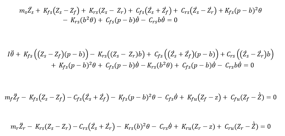
As you can see these locations come in pairs. This is as the differential equations, seen in the attachment, require displacements, velocities or accelerations, that are either end of the real or imaginary spring.
the results from the accelerometers, as well as other sensors, will be output to a raspberry pi that will compare the actual output to a mathematical model (made in simulink) and then... not sure, that's the next bit after the hardware and software. BTW i'm a masters student studying motorcycle engineering, hence the reason for all this.
As for the electronics side of things, above is what i need to accomplish. From what I've found so far, as the MPU6050 and MPU9250 only have 2 addresses, you can't put more than one of each on each bus without conflict from the use of equal addresses. So far my best solution is to use an I2C MUX, but i was looking into the teensy, which has higher i2c speeds, as well as more than one I2C bus.
If you have any recommendations, that will help, i would be grateful to hear them.
If you're using MPU6050 IMUs, there's an easy trick: put them all on the I2C bus, and connect each IMU's AD0 pin to a separate digital pin on the Arduino - . When you want to read from a specific IMU, set all AD0s to HIGH, except the one you want to read to LOW. All the IMUs with AD0 set to HIGH with have an I2C address of 0x69, whereas the only one on LOW will have an address of 0x68. If you want to read them all, you just go through a loop and set the one you want to LOW, the others to HIGH, and you're set.[/i]
Veeery interesting. That could be a lot faster than an MUX. Will give it a try and get back to you. Think i will leave SPI for the moment and do this as it's doing my head in!!
My project involves using around 8 accelerometers to measure multiple aspects of a motorcycles attitude while racing.
Having longer I2C or SPI buses in such a noisy environment won't work (I would expect a bus length of more than 2m given the places you mentioned). I'd suggest to partner every MPU with a small MCU (p.e. an ATtiny) which then communicates with the master by a CAN bus (which was developed with such environments in mind).