Hello and Thanks for the response.
You cleared up a lot of misunderstandings especially with the chip.
Journey of discovery.
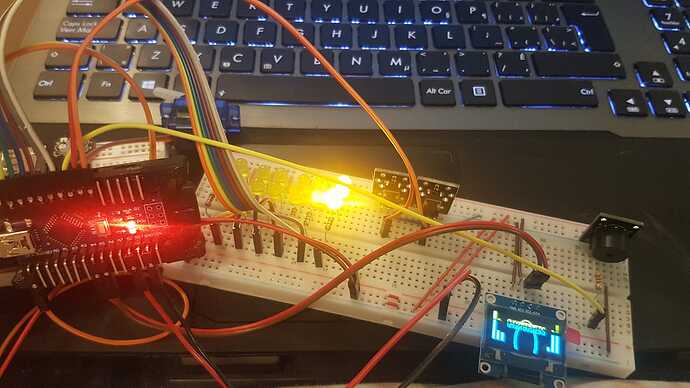
With a little bit of work, I now have sound.
I was powering the unit through a USB powered Voltage Regulator which I guess was not putting out enough mA.
I hooked up a 9V through a Voltage Regulator 7805 to power the project. This fixed the sound problem. So I now have enough mA.
Please see my youtube video for demonstration.
Now all the issue is, that I cannot see the bottom of the screen completely and the words as chopped off (See Video)
Here is the Sketch I am using;
#include <Servo.h>
#include <Adafruit_GFX.h>
#include <Adafruit_SSD1306.h>
#define OLED_RESET 4
Adafruit_SSD1306 display(OLED_RESET);
Servo SERVO1;
int LEDNum = 0; // current LED that is lit
unsigned long previousMillis; // will store last time LED was updated
const int LED1 = 12;
const int LED2 = 11;
const int LED3 = 10;
const int LED4 = 9;
const int LED5 = 8;
const int LED6 = 7;
const int LED7 = 6;
int FILM;
bool SOUND;
const int GB1_PATTERN[7] = {
LED3, LED5, LED7, LED4, LED1, LED6, LED2
};
const int GB2_PATTERN[7] = {
LED3, LED1, LED6, LED4, LED7, LED5, LED2
};
const int DISPLAY_PATTERN[][2] = {
{21, 5},
{18, 20},
{15, 30},
{12, 45},
{9, 50},
{6, 55},
{3, 65}
};
const int BUZZER = 5;
const int BUTTON1 = 3;
const int BUTTON2 = 4;
// know thy button state
bool medium_state = false;
bool high_state = false;
bool button1_down = false;
bool button2_down = false;
void setup() {
pinMode(LED1, OUTPUT);
pinMode(LED2, OUTPUT);
pinMode(LED3, OUTPUT);
pinMode(LED4, OUTPUT);
pinMode(LED5, OUTPUT);
pinMode(LED6, OUTPUT);
pinMode(LED7, OUTPUT);
pinMode(BUZZER, OUTPUT);
pinMode(BUTTON1, INPUT);
pinMode(BUTTON2, INPUT);
digitalWrite(BUTTON1, HIGH);
digitalWrite(BUTTON2, HIGH);
// The following lines are because my PKE setup
// is currently running without the buck converter.
// Pin D2 acts as VCC for the OLED screen
// PN June 12, 2018d
pinMode(2, OUTPUT);
digitalWrite(2, HIGH);
display.begin(SSD1306_SWITCHCAPVCC, 0x3C);
display.display();
// Clear the buffer.
display.clearDisplay();
initialSetup();
SERVO1.attach(13);
SERVO1.write(90);
}
// current display val
int currentVal = 0;
void loop() {
int button1 = digitalRead(BUTTON1);
int button2 = digitalRead(BUTTON2);
if ( button1 == LOW && button1_down == false ) {
button1_down = true;
if ( medium_state == true) {
medium_state = false;
high_state = false;
currentVal = 0;
} else {
medium_state = true;
high_state = false;
currentVal = 40;
}
} else {
if (button1 == HIGH && button1_down == true ) {
button1_down = false;
}
}
if ( button2 == LOW && button2_down == false ) {
button2_down = true;
if (high_state == true) {
medium_state = false;
high_state = false;
currentVal = 0;
} else {
medium_state = false;
high_state = true;
currentVal = 90;
}
} else {
if (button2 == HIGH && button2_down == true ) {
button2_down = false;
}
}
// do the led stuff
LEDLoop(currentVal);
// do the servo stuff
ServoLoop(currentVal);
// delay in between reads for stability
delay(1);
}
void initialSetup(){
String headings[] = {"WHICH PATTERN?", "SOUNDS?"};
String labels[][2] = {
{"GB1", "GB2"},
{"NO", "YES"}
};
for (int i = 0; i < 2; i++){
int button1 = digitalRead(BUTTON1);
int button2 = digitalRead(BUTTON2);
while (button1 == HIGH && button2 == HIGH){
display.setTextSize(1);
display.setTextColor(WHITE);
display.setCursor(22, 5);
display.print(headings*);*
- display.setCursor(10, 30);*
_ display.print(labels*[0]);_
_ display.setCursor(100, 30);_
_ display.print(labels[1]);
display.display();
button1 = digitalRead(BUTTON1);
button2 = digitalRead(BUTTON2);
}
if (button1 == LOW && i == 0){
FILM = 1;
} else if (button2 == LOW && i == 0){
FILM = 2;
} else if (button1 == LOW && i == 1) {
SOUND = false;
} else if (button2 == LOW && i == 1) {
SOUND = true;
}
digitalWrite(BUTTON1, HIGH);
digitalWrite(BUTTON2, HIGH);
delay(500);
display.clearDisplay();
}
}
int prevB = 0;
void drawDisplay(int level, int bar) {
display.setTextSize(1);
display.setTextColor(WHITE);
display.setCursor(29, 5);_
//String display_str = String("GHOSTBUSTERS");
//display.print(display_str);
_ int b1 = random(prevB, bar);
int b2 = random(prevB, bar);
int b3 = random(prevB, bar);
int b4 = random(prevB, bar);
int b5 = random(prevB / 2, bar / 2);
int b6 = random(prevB / 2, bar / 2);
prevB = bar;
display.fillRect(2, display.height() - (5 + b1), 5, b1, WHITE);
display.fillRect(10, display.height() - (5 + b2), 5, b2, WHITE);
display.fillRect(18, display.height() - (5 + b5), 5, b5, WHITE);
display.fillRect(display.width() - 23, display.height() - (5 + b6), 5, b6, WHITE);
display.fillRect(display.width() - 15, display.height() - (5 + b4), 5, b4, WHITE);
display.fillRect(display.width() - 7, display.height() - (5 + b3), 5, b3, WHITE);
display.drawCircle(display.width() / 2, display.height() / 2 + 7, level, WHITE);
display.display();
}
void clearLoop() {
display.clearDisplay();
prevB = 0;
}
void LEDLoop(int convertedVal) {
unsigned long ledSpeed = map(convertedVal, 0, 100, 500, 20);
// check to see if it's time to change the state of the LED*
* unsigned long currentMillis = millis();
if ((unsigned long)(currentMillis - previousMillis) >= ledSpeed)
{
previousMillis = millis();
if (SOUND) {
TriggerBuzzer();
}
if (FILM == 1){
if (LEDNum == 0){
clearLoop();_
digitalWrite(GB1_PATTERN[6], LOW);
_ } else {_
digitalWrite(GB1_PATTERN[LEDNum - 1], LOW);
_ }_
digitalWrite(GB1_PATTERN[LEDNum], HIGH);
_ } else {
if (LEDNum == 0){
clearLoop();_
digitalWrite(GB2_PATTERN[6], LOW);
_ } else {_
digitalWrite(GB2_PATTERN[LEDNum - 1], LOW);
_ }_
digitalWrite(GB2_PATTERN[LEDNum], HIGH);
_ }_
drawDisplay(DISPLAY_PATTERN[LEDNum][0], DISPLAY_PATTERN[LEDNum][1]);
_ LEDNum = (LEDNum + 1) % 7;
}
}
void TriggerBuzzer() {
tone(BUZZER, 2000); // Send 2KHz sound signal...
delay(20); // ...for 20 msec*
* noTone(BUZZER);
}
void ServoLoop(int convertedVal) {
int servoVal = map(convertedVal, 0, 100, 110, 40);
SERVO1.write(servoVal);
}*_


