4 digit 7-segment display (common anode or cathode) with or without 74hc595

Hi guys! I'm new to Arduino and I have trouble understanding the correct wiring of 4 digit 7-segment display (common anode or common cathode) with or without 74hc595 8-bit shift register.
These are the diagrams of common cathode and commom anode 4 digit 7-segment display.


This is the 74hc595 pin diagram.

I want to use multiplexing. Please advise me if what I say is correct:

  1. When using 4 digit 7-segment display (common cathode): I wire the 4 common cathode pins to output pins, set them all HIGH initially and set a specific one LOW to enable a specific digit. Then I wire the 8 anode pins to 74hc595 and light the leds of a single digit simultaneously (as long as I use small current for each digit led, to account for the fact that 74hc595 has maximum total current 70ma, ideally 6ma for each digit led).
  2. When using 4 digit 7-segment display (common anode): I've read many tutorials that claim that I can use the reverse procedure from above: use output pins for the 4 common anode pins and then use 74hc595 to sink the 8 cathode pins. However, I can't understand how this can possibly work! Can an output pin provide power for as many as 8 digit leds???
    For this I believe I have 2 options:
    a) Use output pins for the 4 common anode pins (set them LOW initially) and output pins for the 8 cathode pins (set them HIGH initially), set HIGH an anode pin of a specific digit and then cycle through the 8 digit leds, having only one set LOW at any time, so that only one led is powered each time. In that way, I have to cycle through 4x8=32 leds.
    b) Use 5v pin together with 4 PNP transistors to connect them to the 4 common anode pins (so that I have enough power for all 8 leds of a digit to light them simultaneously) and use 74hc595 for the 8 cathode pins.

Do I have any error in my logic?

EDIT: Perhaps I can't even do the common cathode with outpins too and need NPN transistors? How can an output pin set to LOW sink the current of all 8 digit leds?

Don't do either. Use a MAX7219.

Plenty available on little PCBs ready to connect - or already assembled with a 4 or 8-digit display - on eBay.

If you want to do this "for the educational exercise", then proceed as you are, but if it is for a serious project which requires a bright display, go get the MAX7219. :grinning:

It's purely educational, that's why I'm not using MAX7219.
Can I use output pins instead of transistors? But how can an output pin source or sink current for all 8 digit leds simultaneously?

Just make the segment resistors 2k2 and that will limit the digit current to something the Nano can handle.

Aah, I see. So that each segment gets (5v-2v)/2200=1.3ma of current and lights dimly, but all leds sum up to 10.4ma, well below 20ma of the safe maximum of an output pin, correct?

Wizard13:
It's purely educational, that's why I'm not using MAX7219.
Can I use output pins instead of transistors? But how can an output pin source or sink current for all 8 digit leds simultaneously?

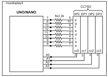
1. Let us build the following multiplexed 4-digit cc-type display unit. In a multiplexed display unit, the segment pins of the identical segments are shorted together except the cc-pins which are separately driven by IO lines.
muxdisplay4.png
Figure-1: Multiplexed display unit.

2. Let us write codes to operate the above display unit as a 4-digit counter of range: 0000 - 9999.

muxdisplay4.png

Addressing your issue in (2), it should work the same in both directions. I believe the 328P sources or sinks the same amount of current per I/O pin. The datasheet should confirm that. So if a pin can sink 8 segments of current from a common cathode display, it should also be able to source 8 segments of current to a common anode display. The issue, as you say, is how much current that will be. The HC595 should work the same way, and it has its limits just as the Arduino does, both per pin and in the aggregate. I think typically you will see people use transistors on the CA/CC pins to transfer the current burden away from the Arduino while still having bright displays.

Note that there is a difference in the efficiency of 7-segment displays. I have found the Vishay displays such as the TDSR1360-IK to generate a lot of light with very little current. There may be others like that.

But I want to address your option in (2a). I had the same idea, motivated by the prospect of being able to do away with all of the segment resistors, and the CA/CC transistors, and have only a resistor on each CA/CC line. That works if you're only turning on one segment at a time. But in the end I settled on multiplexing by turning on the seven (or eight) segment drivers one at a time, but also turning on the CA/CC lines of all of the digits which should have that segment turned on.

So if you are displaying "8888", you would turn on segment A along with all four of the CA/CC lines. Then you would do the same for segment B, and so forth. But for "4444", none of the CA/CC lines would be turned on for segment A.

The maximum current a segment line will have to source/sink is for four segments, not eight. And each CA/CC line never sources/sinks more than one segment. So you only need one resistor in each CA/CC line, and no resistors in the segment lines.

If I/O pins are scarce, an HC4017 would take the place of the HC595.

I thought this was so nifty that I made a video on it, and did a Github repo with demonstration sketches. The downside is that you have to refresh more often, but not really that much more often. For four digits using the traditional method, each digit is ON 1/4 of the time. In the alternate method, each segment is ON 1/8 of the time. So basically you have to refresh twice as often to prevent flicker.

ShermanP:
A In the alternate method, each segment is ON 1/8 of the time. So basically you have to refresh twice as often to prevent flicker.

In a 4-digit multiplexed display unit, for how long time the cc-pin of a digit could be hold at Logic-Low state so that the message at other digit positions does not appear to be absent (aka flickering). To say in other way, what is the frequency of the walking-0 signal across the cc-pins of the display unit. The famous 8279 chip was using a 100 kHz scanning circuit to refresh the 16-digit multiplexed display unit. At this standard, the refresh time for a cc-pin is maximum: 1/100^3 = 100 us.

GolamMostafa:
In a 4-digit multiplexed display unit, for how long time the cc-pin of a digit could be hold at Logic-Low state so that the message at other digit positions does not appear to be absent (aka flickering). To say in other way, what is the frequency of the walking-0 signal across the cc-pins of the display unit. The famous 8279 chip was using a 100 kHz scanning circuit to refresh the 16-digit multiplexed display unit. At this standard, the refresh time for a cc-pin is maximum: 1/100^3 = 100 us.

It doesn't need to be anywhere near that fast. In the example shown in the video, I switch from one segment to the next every 2ms, which is 500 Hz. But that means the same segment is refreshed every 14ms, which is 71 Hz. If I had used the decimal point, it would have been 16ms, or 62.5 Hz. There is no flicker at that rate.

With this alternate method, the refresh rate does not depend on the number of digits. This is multiplexing by segment, so you cycle through the segment lines one at a time no matter how many digits are used. The number of digits only affects how much current the segment lines must source or sink.

With the traditional multiplexing by digit, to get the same 62.5 Hz refresh rate per digit, you would have to switch from one digit to the next every 4ms, which is 250 Hz. But with that method, the rate does depend on the number of digits.

I've never used the 8279, but it appears to be capable of driving much more complicated displays. Perhaps that is why the refresh rate is so high.