I started on this page about a DIY intervalometer. The cheap ones I've tried were quite limited in options and this one seemed like a nice package design. It's designed to work with Nikon DSLR but I use Canon DSLR which has a different handling. Fortunately it's easy to change it.
A couple months ago, I got started on it. The prototype worked but it looked like crap plus I didn't plan to keep the whole thing on breadboard as pieces can wiggle loose during transport and from heat and cold cycle. So I decided on a more permanent solution using Eagle. (still learning KiCad so that will be a while)

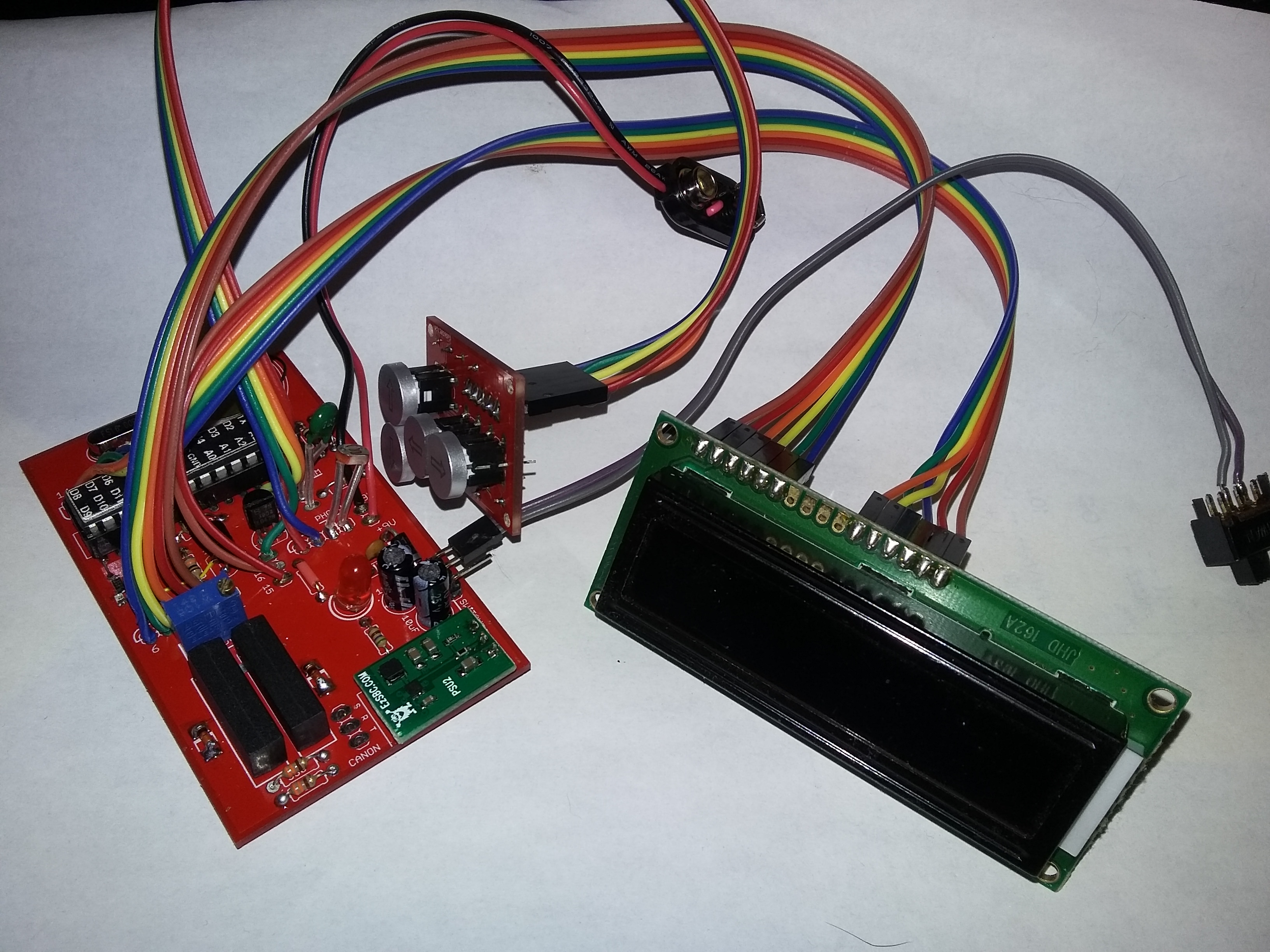
I choose red because why not? Green version would have been about $8 cheaper in production run of 5 PCBs but I am sick of green so I went with red.
Populated board:
parts used:
5x 10k 1/8w resistors
4x 330k 1/8w resistors (on switch board)
2x 560 1/8w resistors (1 on switch board, 1 on main board)
1x resistor 1/8w or jumper depending on the LCD you have. Some has built in current-limiting resistors for backlight, some don't have any and needs external resistors, and some LCD don't use backlight
2x 2N3904 transistors
1x piezo with wires or 0.6" pin spacing
2x NO non-latching SPST relay wih 5v coil such as [url=https://www.digikey.com/product-detail/en/comus-international/3570-1331-051/1835-1116-ND/7497098]this reed relay[/url]
1x 28 pin socket for IC
1x ATMega328p IC programmed (no communication access on this board, you will need Uno board or something to program it)
2x diode SMD such as 1N4148
1x general power diode such as 1N4001
2x 10uF electrolytic cap
2x 0.1uF ceramic
2x 22pF ceramic
1x 16MHz xtal
4x push button switch, LED light optional. 5x5mm standard square button switch with 6.5mmx4mm pin spacing)
1x 7805 or switching regulator equivalent (recommended switching version for battery use)
1x switch (or use jumper if it'll be connected to non-battery source)
1x LED 5mm
1x variable resistor (I used 20-turn because it's what I had when I started drawing in Eagle)
1x thermistor 10k
1x photoresistor
1x 5 conductor cable to switch board
2x 6 conductor cables to LCD
some pin headers on LCD and switch board so those can be separated without desoldering
Solder challenge: slightly hard due to a few SMD components
If you use LCD without backlight and non-lighted button, omit 2N3904 x1, 560 x1 and 10k x1 since it'd be doing nothing.
I made a few changes from the original version on the web site. The power switch was moved to before the regulator because otherwise the battery will get drained through regulator, I used a switching regulator in place of standard 7805 for better efficiency since it'll be mostly off battery, changed the 2 transistors from Nikon version to use reed relay for focus and shooting fro Canon. (it could probably be adapted back to Nikon version, schematic is on the site above, you'd need to change wiring just a bit for 2 lines out rather than 3 lines out) and the 4 buttons for navigating the menu using light up arrow buttons.
These buttons are what I used and it does look bright at 5v with 560 ohms resistor. (12v is probably search keyword spam, LEDs itself are 2-3v). The lighted button turns off when the LCD backlight is turned off (option within menu in Arduino). I failed to account for button cap size and had to file 2 buttons so they could be mounted close together. The revised PCB is 0.05" wider for this.
I did make a minor change to my first permanent prototype after I put it together, I added a couple SMD resistors and SMD LEDs to the focus and shoot pin (on Arduino side, between ATMega chip and wires in the above picture) so I could see the status of focusing and shooting while the LCD is off.
With LCD on and LED button, the whole unit draws about 45mA standby and 55mA using the relay. When LCD is off, it goes down to 25mA and 40mA but another 5mA can be knocked off by not using the 2 status LEDs I added.
I did need to change the code, one line was bugging out. I don't know if it's because there's been a lot of changes with Arduino IDE or with LCD library, lcd.write(0); no longer worked. So I updated for IDE 1.8.x
Hopefully I can change a few things in the code so the settings will be saved to built in EEPROM and loaded on power on. That way I could have a preferred setting such as focus on/off, number of shots, duration between shots, backlight on or off, etc.
I still have 4 sets of blank board left. My board-to-board wiring layout was a tad messy as I didn't arrange to have all 12 pins for LCD or 5 pins for switch board in one place
Eagle file if you want to revise, clean up wiring a bit, make alterations, change to Nikon version, or to figure out something. The solder spot label 2, 3, V, G, and L all goes to switch board. label 1-6, 11-14, 15, and 16 goes to LCD (7-10 are not used on LCD) I have already adjusted the switch board so the button caps will not collide anymore and added LED status next to ATMega chip for focus and shooting.
Note on schematic there is 2 16MHz xtal. This is because there are 2 common sizes, 0.1" and 0.2" pin spacing. I had it overlapping on PCB so I could use whichever I end up getting. I have not made a custom library to combine the PCB pads to one symbol.