Hi to all
I just bought this TFTLCD Touch Screen
for some experiments.
The problem is that i do not know how to connect to my arduino mega and what libraries i have to use.
I am new to arduino and i would apreciate any help.
Thank you,
Yannis
Hi to all
I just bought this TFTLCD Touch Screen
for some experiments.
The problem is that i do not know how to connect to my arduino mega and what libraries i have to use.
I am new to arduino and i would apreciate any help.
Thank you,
Yannis
The display requires 3.3V logic.
You can connect it to your 5V Mega2560 via 13 level shifters.
Life is much simpler if you just buy a proper 3.3V Arduino e.g. Zero, Due, Teensy3.x, ...
MCUFRIEND_kbv library has always supported Renesas R61509V controller.
I am not aware of any other library but I can show you what is required.
David.
Thanks for the reply.
So can i connect it to my UNO without shifter?
Because i don't know where to connect the pins.
I attach an image of the pins in the TFT display.
I would be very greatful if you can show me the connections with Arduino UNO.
Thank you
Yes, of course you can connect to your genuine 5V Uno WITH exactly the same level shifters that you would use for your 5V Mega2560.
If you have a Uno clone with switchable 3.3V / 5V GPIO, you can just select 3.3V.
That is what I do with my Seeeduino boards.
David.
And the other pins of display?Where to connect?
Connect them to the same pins as Mcufriend Uno shields. Then MCUFRIEND_kbv will work exactly the same with your display.
Personallly, I just soldered a 16x1 female header to a Protoshield and wired it to the Mcufriend scheme.
My 2.0 inch display plugs into the socket. The Protoshield plugs into Zero, Due, STM32, Seeeduino, ....
Your 3.0 inch R61509 is just a bigger version of my 2.0 inch ILI9225 display.
David.
Where can i find the connection between my display and Mcufriend Uno shields?
I seached and i did not find something.
Go on. You did not try very hard.
There is little point in worrying about the connections until you have wired up all the level shifter channels.
From LCD_ID_readreg.ino
//-- Arduino UNO or Mega 2560 Plugged as shield
#define LCD_RST A4
#define LCD_CS A3
#define LCD_RS A2
#define LCD_WR A1
#define LCD_RD A0

#define LCD_D0 8
#define LCD_D1 9
#define LCD_D2 2
#define LCD_D3 3
#define LCD_D4 4
#define LCD_D5 5
#define LCD_D6 6
#define LCD_D7 7
In case you do not understand, the 3.3V pin goes to 3.3V pin on the Zero, Due, ...
And the GND pin goes to the GND pin on the Zero, Due, ...
If you are using a genuine Uno, the Uno 3.3V regulator is not good enough for the display backlight current. Use an external 3.3V.
Uno clones with switchable 3.3V probably have a bigger 3.3V LDO regulator.
David.
Thank you very much for your help.
I will try it and i will teply here.Your help is presious.
Finaly i get an answer from the people i bought the display.
They sent me this link to download the library they use for the display.
They olso sent me the pins connection with arduino.
// TFT Breakout  -- OPEN-SMART UNO Red
// GND              --    m
// 3V3              -- 3.3V
// CS               -- A3
// RS               -- A2
// WR               -- A1
// RD               -- A0
// RST              -- 2..
// LED              -- GND
// DB0              -- 8
// DB1              -- 9
// DB2              -- 10
// DB3              -- 11
// DB4              -- 4
// DB5              -- 13
// DB6              -- 6
// DB7              -- 7
I tried the examples and it works fine.
The only thing that it does not work is that i have to connect 3.3V pin to 5V pin in my arduino UNO R3.
But then the background of the the display is gray and not black.
I think that it is because of the wrong voltage but i would like to know if there is a way to solve it.
When i connect the pin to 3.3V i can get the screen shows only when i press the reset button in arduino board.
I have these shift level convertes but i don't know hot to connect to my display.
If anyone can help me please.
I looked at the ZIP and the MKV video from your link.
Open-Smart have simply hacked an obsolete version of my MCUFRIEND_kbv library. And amended some of my examples. I would be perfectly happy if they had chosen a new name for their hacked class,
This gives all sorts of problems if you install the correct MCUFRIEND_kbv library via the Library Manager.
However, they do add this explanation to their sketch:
#include <MCUFRIEND_kbv.h>
MCUFRIEND_kbv tft;

//***********************************************//
// If you use OPEN-SMART TFT breakout board                 //
// Reconmmend you to add 5V-3.3V level converting circuit.
// Of course you can use OPEN-SMART UNO Black version with 5V/3.3V power switch,
// you just need switch to 3.3V.
// The control pins for the LCD can be assigned to any digital or
// analog pins...but we'll use the analog pins as this allows us to
//----------------------------------------|
// TFT Breakout  -- Arduino UNO / Mega2560 / OPEN-SMART UNO Black
// GND              -- GND
// 3V3               -- 3.3V
// CS                 -- A3
// RS                 -- A2
// WR                -- A1
// RD                 -- A0
// RST                -- 2
// LED                -- GND
// DB0                -- 8
// DB1                -- 9
// DB2                -- 10
// DB3                -- 11
// DB4                -- 4
// DB5                -- 13
// DB6                -- 6
// DB7                -- 7
If you look at the video at 0.08 minutes, you can see that they use a switchable 3.3V / 5 V Uno clone.
And at 0.09 you can see his thumb switch the GPIO from 5V to 3.3V
I recommend that you buy a switchable clone e.g. red switchable clone or this blue switchable clone
If you can find the Open-Smart switchable clone that is in the video, that would be good too. Found open-smart black switchable clone
Personally, I have owned and used Seeeduinos for many years. I almost always use them at 3.3V.
Regarding your level-shifters. You must provide a good 3.3V supply because the 3.3V regulator on a Uno is not big enough. (the switchable clones all have bigger 3.3V regulator chips)
And then connect all your signals via the level shifter channels.
This is quite simple to do via a Protoshield. i.e. mount 16x1 header, 3.3V regulator, level-shifters.
Of course, it is much simpler to just buy a 3.3V Zero, Due, ... or switchable Uno. You still need the Protoshield but you avoid all the level switching.
David.
Thanks for the answer.
I will do some more test.
After 3 months i finally find some time to test my display again.
It works fine with Arduino UNO R3 without a shift converter.
I just connect the 3V3 pin of th display to 5V of arduino.
Thanks everyone for the help.
Hello
I have one display similar to jxid, from aliexpress:
DIYmall 3.0" 3.0inch TFT Touch Screen Shield Display Module 400*240 Pen (couldn't put the link)
and a Arduino DUE (already 3V3 I/O).
After a few unsuccessful attempts to make the display work, I decided to follow David's tips from this post, using his MCUFRIEND_kbv library.
I have used this hardware configuration:
RST A4
CS  A3
RS/CD/XM  A2
WR/YP  A1
RD  A0
LED  Gnd
D0  8
D1  9
D2  2
D3  3
D4  4
D5  5
D6/XP  6
D7/YM  7
and it worked fine for me, running the graphictest_kbv and the TouchScreen_Calibr_native examples.
Thank you David, for your tips and patience here and in the other posts.
Greetings from Brazil
kaefe
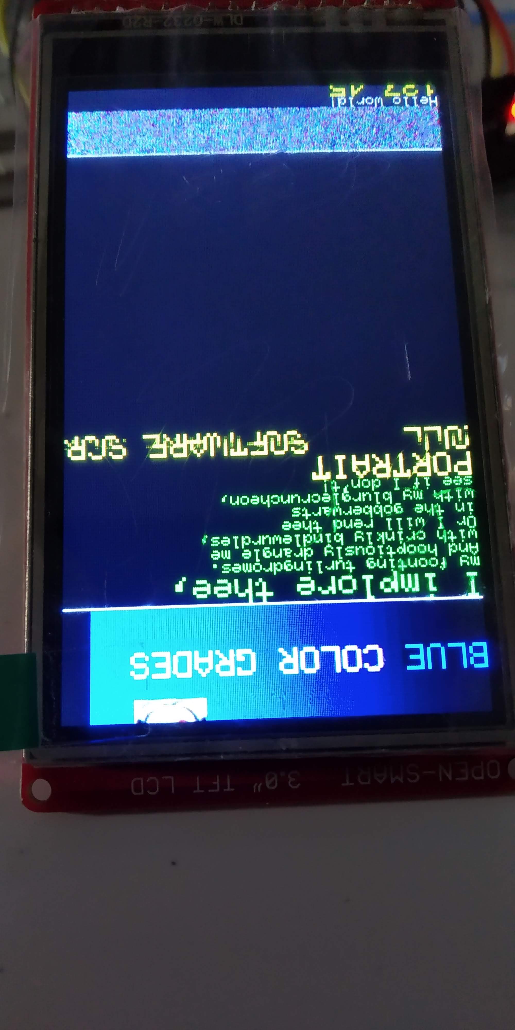
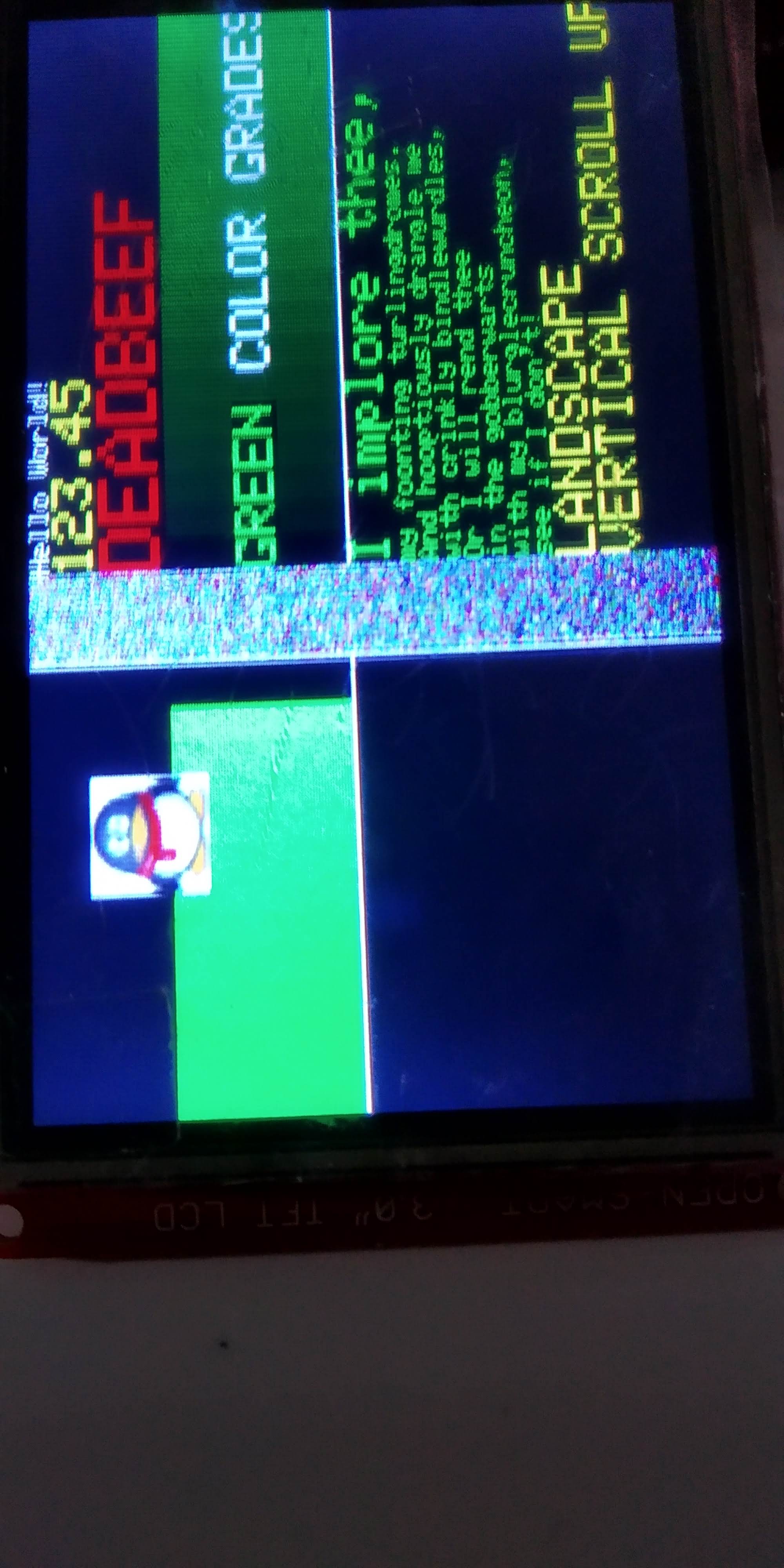
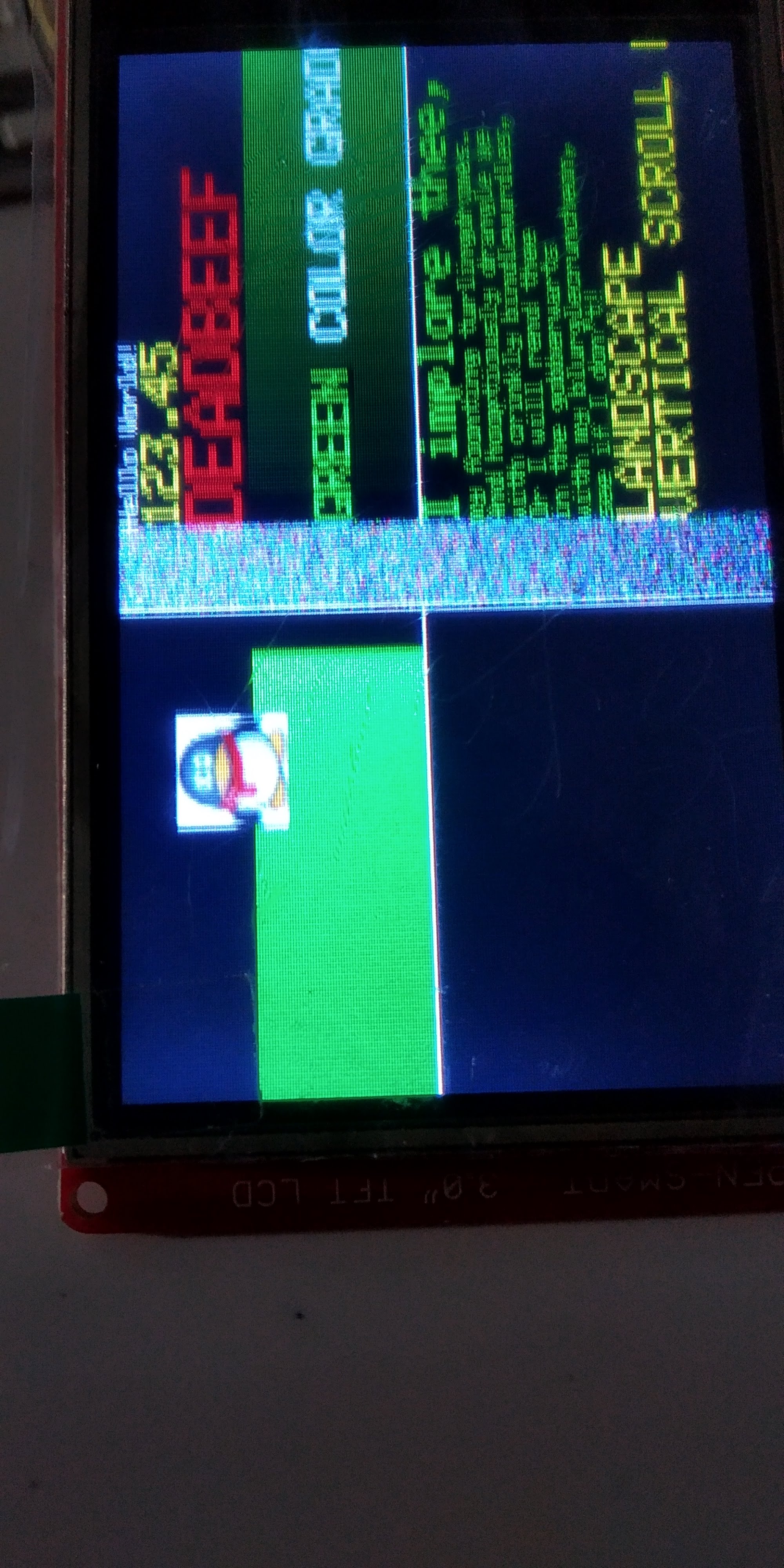
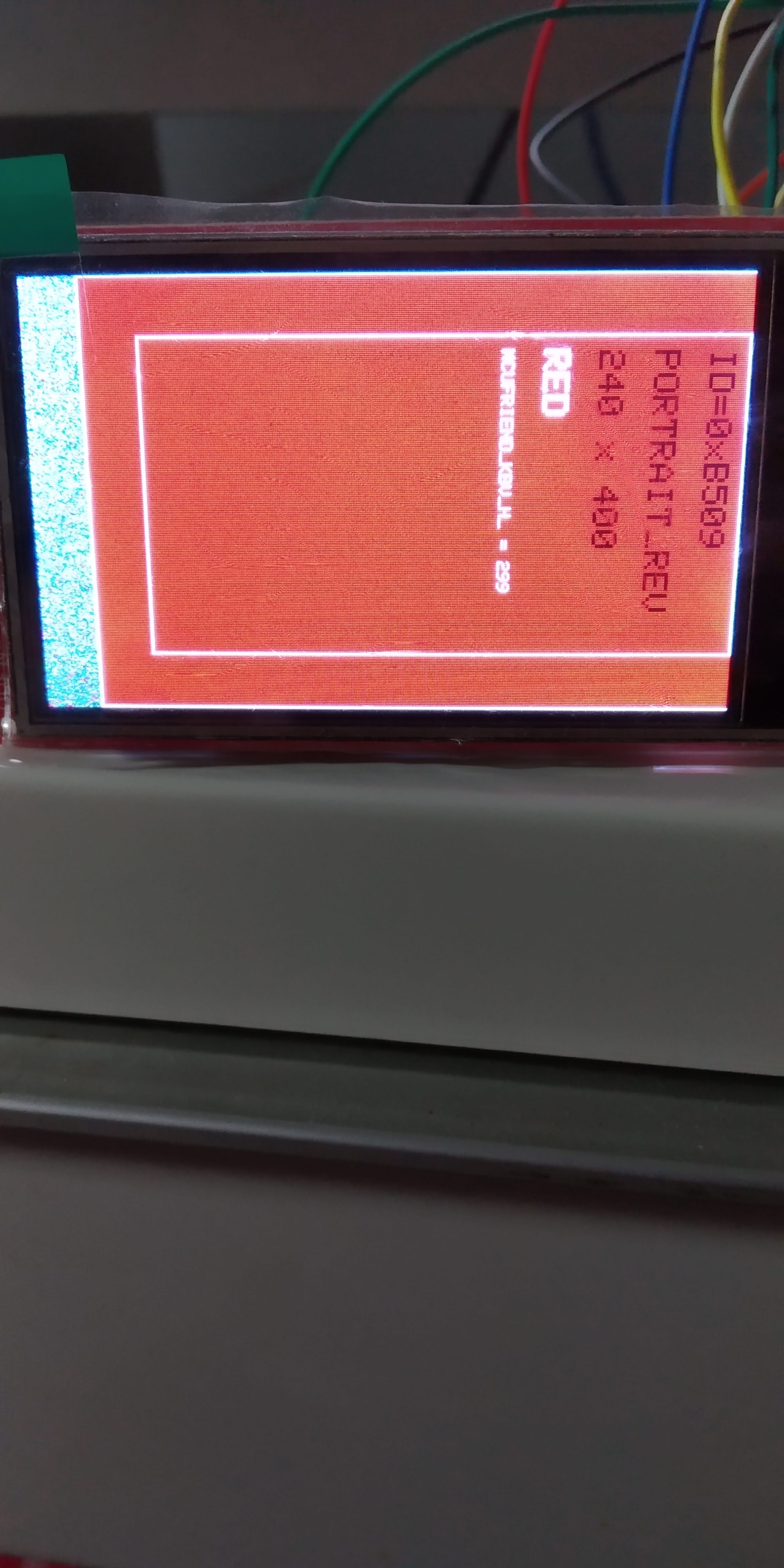
Now i am trying mt 3.0" tft lcd display with David's library.
I managed to make it work but i have some issues running the graphicstest.ino.
I am getting noise line accross the screnn in scrolling text with pinguin.
At the first screen with colors and lines the display works fine.
I attach photos to see what i mean.
Is there any explanation for it?
Thanks.
Please post a link to the screen that you have bought e.g. Ebay sale.
Please say which controller is reported by tft.readID()
It takes little time to provide information.
It makes all the difference to getting accurate replies.
Most importantly, you get an answer with one reply instead of the thread running into multiple messages for days.
David.
I bought the display from 3.0" TFT LCD Display
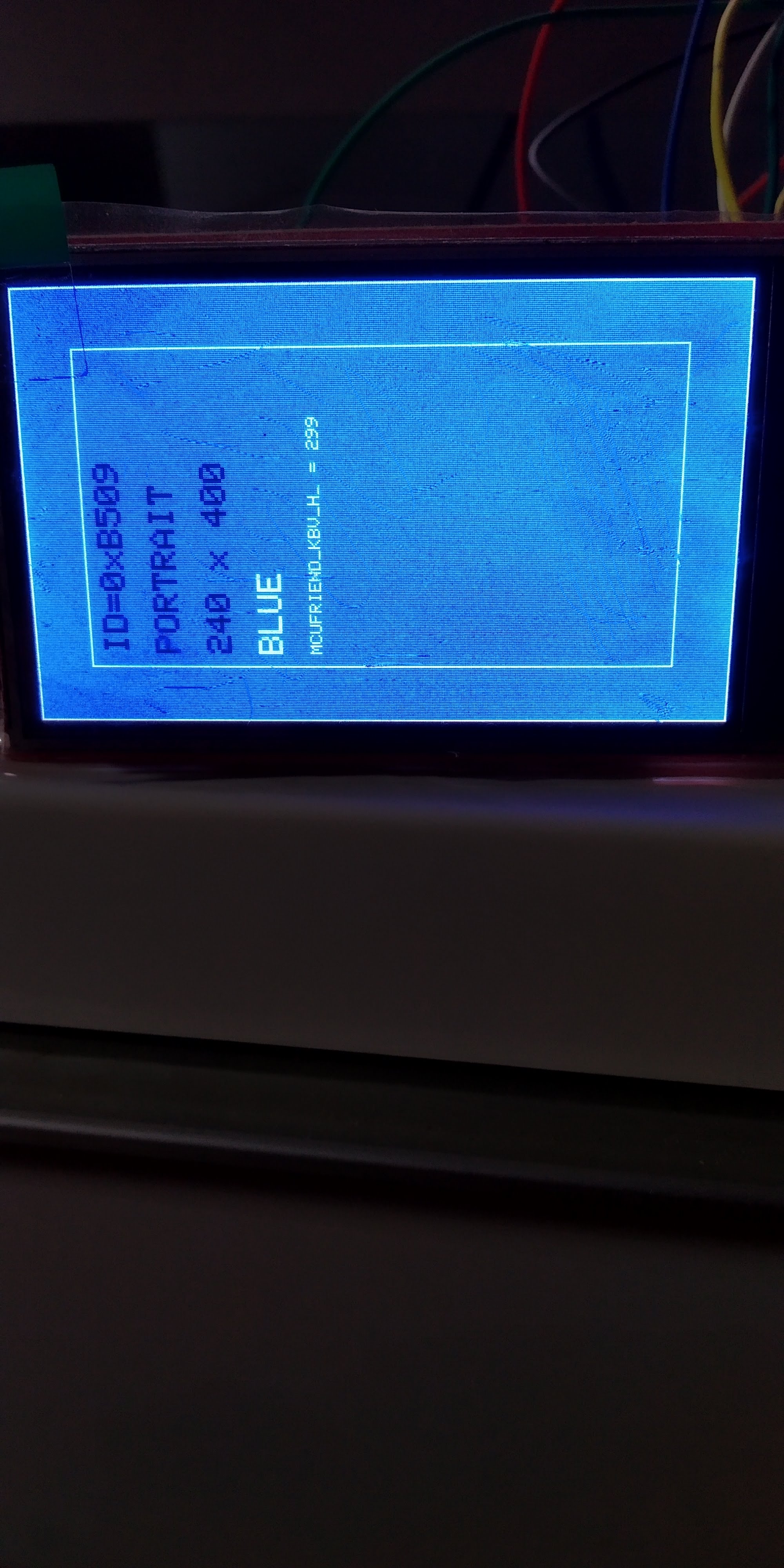
This is what diagnose_TFT_support.ino shows:
Diagnose whether this controller is supported
There are FAQs in extras/mcufriend_how_to.txt

tft.readID() finds: ID = 0xB509

MCUFRIEND_kbv version: 2.9.9


PORTRAIT is 240 x 400

Run the examples/graphictest_kbv sketch
All colours, text, directions, rotations, scrolls
should work.  If there is a problem,  make notes on paper
Post accurate description of problem to Forum
Or post a link to a video (or photos)

I rely on good information from remote users
I use the constructor:
GND  ———-  GND
3V3  ————  5V (3.3V)
RST  ———-  A4
CS   ———-  A3
RS   ———-  A2
WR   ———-  A1
RD   ———-  A0
LED  ———-  GND
DB0  ————  8
DB1  ————  9
DB2  ———-  2
DB3  ———-  3
DB4  ————  4
DB5  ————  5
DB6  ————  6
DB7 ———— 7
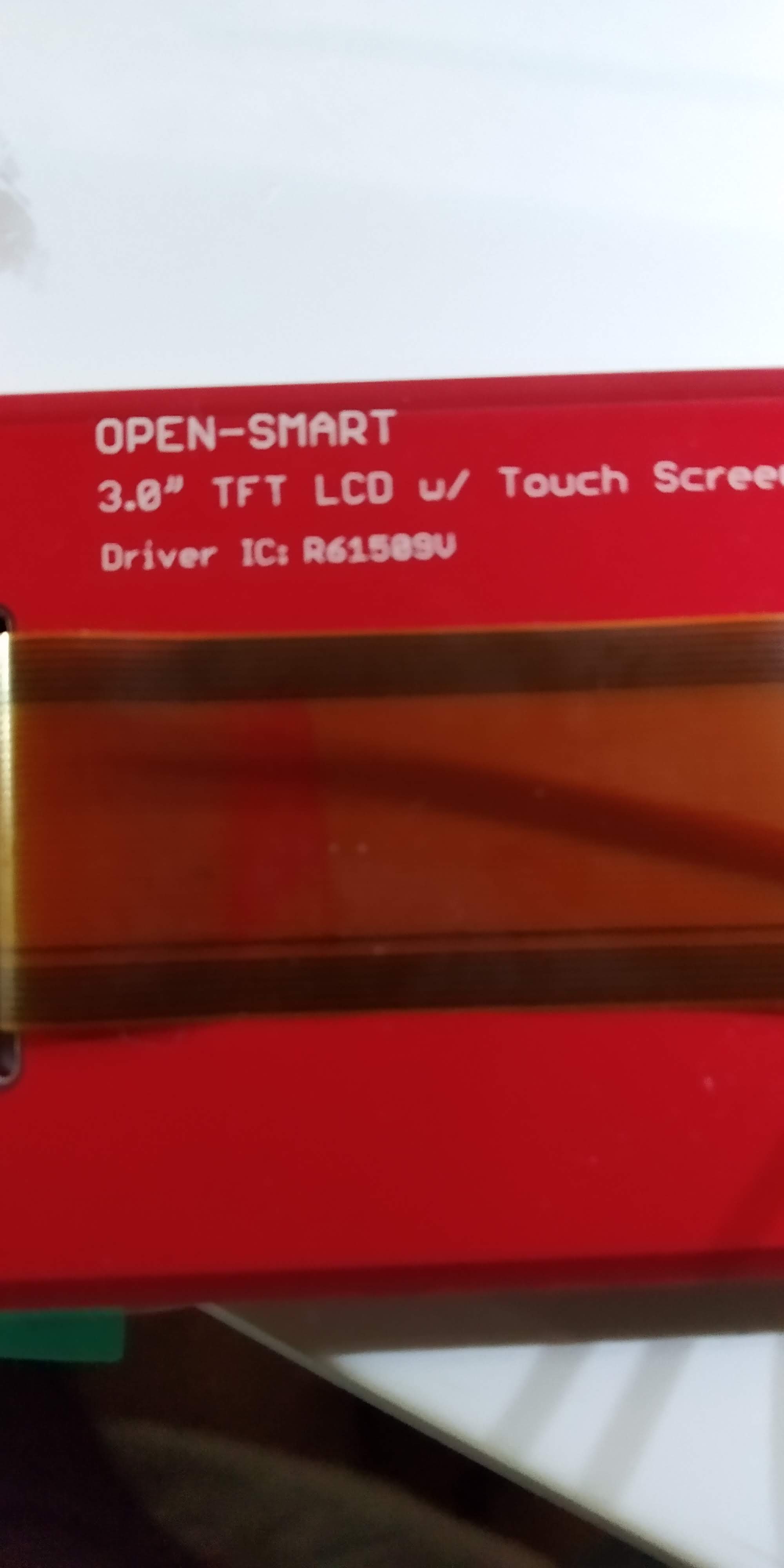
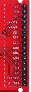
And i attach a photo of the back of my dispaly.
It says that the driver IC is R61509V
You have a Renesas R61509V controller.
The board is 3.3V with NO level shifters.
The controller is 240x432 but the panel is 240x400. You see random pixels 401-432 when it scrolls the whole screen.
I gave my R61509V shield away. So I no longer have this controller.
I can't use the ILI9327 trick because the R61509V does not support Band Scrolling.
I might have another method but your board is unlikely to survive your cavalier 5V.
David.
david_prentice:
You have a Renesas R61509V controller.
The board is 3.3V with NO level shifters.The controller is 240x432 but the panel is 240x400. You see random pixels 401-432 when it scrolls the whole screen.
I gave my R61509V shield away. So I no longer have this controller.
I can't use the ILI9327 trick because the R61509V does not support Band Scrolling.
I might have another method but your board is unlikely to survive your cavalier 5V.David.
Thanks for the answer.
Hi David,
I am writing to this thread because I have the same TFT display as jxid and I want to spare you all the trouble identifying the details.
My display works fine with Seeeduino UNO clone and the MCUFRIEND_kbv library. (I do not care for the random pixels at the extra lines 401-432 yet).
I want to connect this display to ESP32. For some reason, the MCUFRIEND_kbv library does not mind when I select the ESP32 dev module and verify the compile.
Would MCUFRIEND_kbv library really work with ESP32 ?
I have wired a custom "shield", inspired by the D1 R32 board that Bodmer (is that you?) used for testing 8 bit Mcufriend UNO shields. The reason, that I wired a custom shield was, that I needed an ESP32 with PSRAM to be able to process the bitmap and I didn't find an UNO board with ESP32 with PSRAM. So my shield is exactly like the D1 R32 on GitHub - Bodmer/TFT_eSPI: Arduino and PlatformIO IDE compatible TFT library optimised for the Raspberry Pi Pico (RP2040), STM32, ESP8266 and ESP32 that supports different driver chips with the extra connections on the back
I only made extra wiring for the one row of pins on the TFT display.
I probably will have to add an extra 3.3V supply to that wiring as you mentioned a couple of times.
And I want to use the TFT_eSPI library.
My questions are:
Is the driver name significant for parallel control? And if so, what is the driver name? (the R61509V is not among the TFT_Drivers folder in the TFT_eSPI library). Actually this is a question that you already mentioned talking about ILI9327 trick, that can not be used with this display. Can you find another trick, that would work?
I guess the best way is to create a User_Setup file following the SetupX_Template.h like:
// ######       EDIT THE PINs BELOW TO SUIT YOUR ESP32 PARALLEL TFT SETUP        ######

// The library supports 8 bit parallel TFTs with the ESP32, the pin
// selection below is compatible with ESP32 boards in UNO format.
// Wemos D32 boards need to be modified, see diagram in Tools folder.
// Only ILI9481 and ILI9341 based displays have been tested!

// Parallel bus is only supported on ESP32
// Uncomment line below to use ESP32 Parallel interface instead of SPI

#define ESP32_PARALLEL

// The ESP32 and TFT the pins used for testing are:
#define TFT_CS   33  // Chip select control pin (library pulls permanently low
#define TFT_DC   15  // Data Command control pin - must use a pin in the range 0-31
#define TFT_RST  32  // Reset pin, toggles on startup

#define TFT_WR    4  // Write strobe control pin - must use a pin in the range 0-31
#define TFT_RD    2  // Read strobe control pin

#define TFT_D0   12  // Must use pins in the range 0-31 for the data bus
#define TFT_D1   13  // so a single register write sets/clears all bits.
#define TFT_D2   26  // Pins can be randomly assigned, this does not affect
#define TFT_D3   25  // TFT screen update performance.
#define TFT_D4   21
#define TFT_D5   22
#define TFT_D6   27
#define TFT_D7   14
I guess the TFT_DC corresponds to the RS pin on the display.
Thank you for being with us ![]()
We do not always tell, how much we appreciate your advice.