Hi Guys, I am currently trying to reverse engineer some CAN BUS packages from an elevator control so that I can eventually send signals to a display unit and change the floor and arrow direction on the said unit.
The problem I am having is that I cant seem to get any data off the CAN BUS of the Controller. >:(
I am using a Arduino Uno and Elecfreaks CAN BUS shield to connect to the elevator CAN BUS. When I connect the arduino and shield (after uploading the code) the Rx LED on the shield flickers (which to me should be an indication of data being received) but when I open the monitor there is no data being logged (I used the Arduino software and tried using puTTY to get data)
I should mention that I am not using the DB9 plug I am using the CANH and CANL terminals
My code is as follows (Code from Martin's Super Sniffer)
//This Arduino UNO Sketch requires the Seeed CAN-BUS Shield Libraries
//GitHub - yexiaobo-seeedstudio/CAN_BUS_Shield: Seeed Studio CAN BUS Shield library
#include <SPI.h>
#include "mcp_can.h"
INT32U canId = 0x000;
unsigned char len = 0;
unsigned char buf[8];
char str[20];
void setup()
{
Serial.begin(9400);
START_INIT:
if(CAN_OK == CAN.begin(CAN_250KBPS))
{
Serial.println("CAN BUS Shield init ok!");
}
else
{
Serial.println("CAN BUS Shield init fail");
Serial.println("Init CAN BUS Shield again");
delay(10);
goto START_INIT;
}
}
void loop()
{
if(CAN_MSGAVAIL == CAN.checkReceive())
{
CAN.readMsgBuf(&len, buf);
canId = CAN.getCanId();
Serial.print("<");Serial.print(canId);Serial.print(",");
for(int i = 0; i<len; i++)
{
Serial.print(buf*);Serial.print(",");*
- }*
- Serial.print(">");*
- Serial.println();*
- }*
}
[/quote]
I have tried changing the Can speed but nothing changes
I have also tried two different shield,one with the track above CANH and CANL cut and one that is not cut. I read somewhere this has to do with the 120ohm resistor for the can bus
Do you guys have any help for me?
Are you sure you got he correct CAN H and CAN L lines? Use a multimeter to measure, they should have around 2.5V when the BUS is IDLE.
For sniffing the data I highly recommend using a RPI + CAN Bus module/HAT. There are some great tools for that.
Finally, the resistor should only exist on the end of the bus, so if you're hooking your "node" in the middle, the existing system should already have the resistors in place.
From your code, can you at least see the message "CAN BUS Shield init ok!" in the serial console? I noticed you're using an weird Serial speed of 9400... change it to 115200 and make sure Putty/Serial Monitor is in the same speed!
Thanks for the reply.
I measured the voltage on the CAN BUS, voltages are as follows:
With end-display resistors off (CAN BUS led solid on)
CANL - CANH = 2.073V
COM - CANL = 1.312V
COM - CANH = 3.383V
With end-display resistors on (CAN BUS led fickering)
CANL - CANH = 0.2V
COM - CANL = 2.14V
COM - CANH = 2.34V
I am curious, do I need to ground my arduino to the elevator system so that they have a common ground?
I will try changing the serial speed to 115200 (only set the speed to 9400 because putty had it asstandard)
As for the serial monitor and putty display. They display CAN BUS Shield init okay, everything looks good up to the point where data needs to be flowing into my life, haha. But no Data
One more question, I am not too sure as to what the baudrate is on the system, I have tried all the baudrates I could think off but that obviously also didn't help.
What will happen if the wrong baudrate is selected? should there be data coming in? or would that prevent data from coming in?
Thanks a ton for the help
Jacques Nel
Okay so I tried your previous suggestion of setting the serial speed to 115200 and ensured putty and the monitor was on the same setting.
Same results tho, the Rx led goes bonkers, the init is all good but no data coming in.
Enter setting mode success
set rate success!!
Enter Normal Mode Success!!
CAN BUS Shield init ok!
I even tried grounding the arduino to the display, nothing??
I have been puling out my hair here everything should work? but doesn't..
What do you mean by end-display resistors?
The 2.5ish volts seems fine... You would have some differences when data is flowing.
You shouldn't need to connect ground as the voltage levels are only based on the difference between Can H and Can L... But you might wanna try as last resource.
Regarding the speed, if you get it wrong no data will appear, most likely because the CRC will fail or the frames will look odd to the controller. A scope would be the best to check the speed and sniff the bus... But there are many speed options, so make sure you try all. Also check if you library is using the correct crystal value as the timings for the speed is based on that.
Each Display has a switch at the back that turns the 120ohm resistor on or off, during installation the installer switches the last display resistor on (far end of can bus)
I have tried all the speeds I could google?
10, 20, 50, 100, 125, 250, 500 and 1000 kbps.
Am I missing a few?
Note: I am very new to electronics and coding so I am still learning.
How would I ensure that the library is set to the correct crystal value? where and how do I change this? also what value do I change it to?
Thanks again
Which library are you using? From which site? Also, what's the crystal frequency from the CAN Bus shield? Just look at the component, should br write on the top.
Finally, do you have only one Can Bus shield? If you have two you could try to make two arduinos talk to each other to make sure they're working.
I currently have 3 Libraries installed, the seeed library, sparkfun library and elecfreaks library.
I have 4 Elecfreaks CAN BUS shields at the moment, and I have connected them to each other and used the send and receive examples, they work perfectly with the examples no problems.
As for the crystal frequency the writing on the components are 16.000
Something else caught my eye whilst reading through the manual.
The manual says there is a 8 bit binary code that provides as many as 255 output status in accordance with the WORD BANK for display.
There is a list of Standard Word Bank from 0 to 255 each having its own indication.
According to the manual the binary code of each number is sent to the display so according to the list the value 1 should indicate floor 1 on the display (1 in binary that is, so 0,0,0,0,0,0,0,1).
I am assuming that this code is being sent as serial protocol 8,N,1. This is a big guess tho but I am getting desperate now.
Would the code I am using be able to get this data off the controller??
Would this not require much lower baud rates? I read up on the 8,N,1 and wikipedia states baud rates as low as 1200bps would this be possible to code?
One more thing that I found that is troubling my brain.
After you mentioned the crystal and the speed/value on the crystal I had a look at the display board. The crystal component on the display board has a value of 4.000??? Could this not be one of the problems?
Hi again,
a few things:
-
Great you can exchange messages between two CAN Bus shields, that proves your hardware and connections are working
-
Regarding the message format, it doesn't really matter at this point as you still trying to get a message, independent of the content
-
The crystal speed on the boards don't need to be the same, the important part is that the CAN Controller configuration is done correctly, taking in consideration the crystal speed.
-
What CAN Controller chip is being used on the Elevator board? MCP2515? I just wondering if the Board you're trying to communicate with is really a CAN Bus and not something else like RS-485.
-
For the CAN Speeds, there's actually an "infinite" number of options, on the Seed library they have prepared a few more than you listed: GitHub - Seeed-Studio/Seeed_Arduino_CAN: Seeed Arduino CAN-BUS library - MCP2518FD&MCP2515&MCP2551. Looks like the Seed shield also uses a 16MHz crystal, so you should be fine using their library to get the right Configuration for the CAN Controller. If you're interested in CAN Speed (bit timing), here a good calculator link: https://www.kvaser.com/support/calculators/bit-timing-calculator/
-
For the resistors, if you're only trying to connect your Arduino + Can Bus Shield to a single "Display Board", you do need to have the 120R resistors at the end of the CAN Bus itself:
---CAN_L-------|         |-----|       |-----CAN_L---
| 120R         | Arduino |     | Board |            |120R
---CAN_H-------|         |-----|       |-----CAN_H---
Otherwise, if you're "tapping" into an existent bus, you should be find by simply using a small stub from the middle of the bus.
Hi Thanks so much for the reply I have been going mad pulling my hair out.
As for the Display board according to the elevator control manual everything communicates over CAN BUS, but this is a Chinese control we are talking about so something could have been mistranslated. I have checked all over the various displays I have lying in front of me but cant see a MCP2515 chip on any of them.
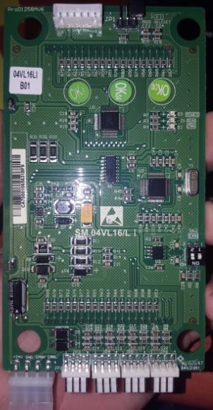
Here is a list of the chips I could make out on one of the boards:
HT16C22 (I believe this is a LCD Controller)
VP1050
96F613RB 1615 NO1 GSA E1
62A5521C UCN2003A
CCS 4.000 crystal
These are all the chips I could make out on the back of the board not sure if one of them has to do with the CAN BUS.
The display however is connected with a 24V+ GRND + CANH + CANL wires (but once again not sure if this indicates that it definitely is a CAN BUS Chinglish is a complicated language)
I have attached pictures of the display for reference.
Thanks again the help is much appreciated and this is the only help I can find, been struggling with this project for 2 months now very frustrating but I am learning a lot so that's good.

The board doesn't look that bad... Those big chips might be ARM MCUs and many co.e with CAN controllers built-in, so you might have the CAN transceiver.
Have you Googled all parts to see what you find? Try to follow the CAN H and L traces...
Also, do you expect to see any CAN message coming from this board?
You mentioned it's a display board, it might work in Listening mode only... Or if it's supposed to be connected to buttons you might need to "press" it so the board send the message to the Bus instead of continually send messages.
The display unit does have buttons connected to the board (UP and DOWN obviously) I have pushed these buttons trying to send a message to the arduino (used both the send and receive code I have been using in every baud rate possible)
But nothing happens.
There should be a message coming from each of the boards (various levels of the building) the displays are set by using a jumper at the top you set each floor (bottom floor set to 1 then floor above that set to 2 and so on) once you insert the jumper the display address is displayed on the screen.
For this project I have set the display to 1 and switched the CAN SW on and off for every test (the CAN sw is only switched on the last display on installations this is the CAN BUS resistor (120ohm)
I have tried googling the individual chips but cant find anything that tells me one of them are CAN BUS related?
I feel like I have hit a wall at the moment? How do I climb this wall?
Oscilloscope is the name of a ladder... Contacting the manufacturer also helps.
I wish I had an oscilloscope, I live in South Africa and they are a bit on the expensive side here.
I have sent the engineers, admin guys and cleaning lady at the company e-mails a couple of times but there is never a reply to my mails. I have downloaded as much info and manuals and datasheets of the controller and display as possible but nowhere (and I have read the 300+page manual on the controller)does it say anything about baud rates or anything useful. Just that there is a CANH and CANL
I think ill have to beg my boss for an oscilloscope, highly doubt he will even consider it tho.
Damn electronics, looks like we have a love hate relationship.
Hope this is just a hobby and not to be used in a real elevator with people inside or near by...
Just a Hobby. A very frustrating hobby that's been driving me crazy.
Besides the elevator display is totally separated from the actual control of the elevator so no danger at all.
Its my idea of learning how the system works, but now has become a challenge and something I can get working which is probably one of the things that irritates me the most.
I need to make it work in order to sleep at night hahaha
Maybe try one of those cheap USB logic analyser... I'm just wondering if the board is actually waiting some message from a main controller or similar to start communicating. But trying to capture it via a scope or a $10 logic analyser would be great fun as well... You can trial between two Arduinos at different speeds, where you know that works... and try on the real boards later