I'm building a "RIMS" control panel. Inside this panel is 120v main that feeds to a water heater element and a pump. This pump pumps water over the heating element, the element is controlled by an Arduino. I'm looking for thoughts if this drawing is safe, do I need fuses, and where should they be? Any other safety measures I need to take?
Power is coming from a 20amp breaker with GFCI protection. Except for low voltage stuff all outlets, switches, wiring, etc will be rated for 20amp for good measure. (I only 'expect' to need 15)
This is for a home brewery so the potential for water splashing around is something to keep in mind. The enclosure will be as water proof/resistant as I can make it.
PS - What ever I do I'd like to make sure that the element can NOT fire if the pump isn't turned on.
I am actually working on a sensor to detect liquid flow, but I still want this physical safe guard. I also didn't want to crowd that drawing with all my low voltage junk. The components not drawn will just be an LCD screen, rotary encoder, some temp probes, and some kind of flow sensor.
Those duplex outlets pictured are usually connected to one another, they have tabs that you can break away to isolate the plugs from each other. I don't think that will be necessary for the double light switch though, I think they are typically only connected on one side anyway, I'll need to update my drawing. Here's a look at a tab: http://i.imgur.com/J0FA2PW.jpg
A single fuse on the hot wire as soon as it enters the box? Would a 20 amp fuse be an appropriate size? Any other protection necessary?
(The ssr will be mounted on a large heat sink that will be poking out of the enclosure)
Yes, your drawing is well done. A 20 amp regular fuse, or circuit breaker, is fine; if all of the wiring is 20 amp such as 12 AWG. Since you are around water, at some time you will damage the solid state relay. Some people would install a super-fast I2T fuse to protect the SSR, but the fuse costs as much as the SSR. I would install a small indicator light on the wire after the SSR's output. This will confirm that it actually goes on/off/on/off as requested. For a 15 amp application, you need a heat sink that is rated about 3.3 C/W or lower. (15 amps x 1.2 thermal rise = 18 watts of heat. 60/18 = 3.3C/W needed) A lower number means that the heat sink is more aggressive.
Since GFI outlets are very low price, I might also install one where you have your 20 amp outlet now. This is in case, when you are not around, someone plugs the system into a different (non GFI) outlet in your shop. Such as when they are mopping the floor. You can't be too careful. Things happen.
Paulcs:
Since you are around water, at some time you will damage the solid state relay.
You make it sound inevitable, is that the case? Would this damage be dangerous? If this fuse costs as much as the ssr would it make more financial sense to just replace them as they are damaged? (Given what ever caused the damage doesn't effect other components)
If you are saying to use gfi outlet in my control panel, the problem with that is the duplex gfi outlets can't be isolated to run on different circuits. I have changed my drawing though to use combo light switch outlet recepticals, maybe I can find those with gfi.
Water damage. Yes, I would replace the SSR when it becomes damaged. I mentioned the I2T fuse, because that it the more technically correct answer, that some blogger might suggest. The reason that the SSR will become damaged: a dead short, such as heater to tank or water splash on wiring, will cause damage. Fuse and circuit breakers have some time delay, since their purpose is to protect copper wire. A SSR is built from a silicon die. It doesn't have any time delay if a dead short happens. So it will become damaged. It will often go "open" when exposed to a dead short. The short "shatters" the internal silicon.
A SSR is capable of failing in an ON mode. That is why I suggested a indicator lamp after the SSR. As long as you see that is turns ON/OFF/ON/OFF as requested, then you know that it is working fine.
I agree with your statement about the GFI outlet, being non-independent-duplex. As long as you are plugged into a main GFI, you are doing well.
Make sure you properly heat sink the SSR for the load.
When you hook up your SSR, route the low voltage (control) lines well away from the mains connections and lines; don't parallel the wires, or even have them near each other.
Make sure to build some kind of shield (plastic or such) over the screw terminals of the SSR.
Also, regarding:
PS - What ever I do I'd like to make sure that the element can NOT fire if the pump isn't turned on.
If you want this to work properly, and simply, then only have a single mains switch to control the mains, then use two SSRs (one for the pump, one for the element). Then build your control panel to use other switches or buttons which tell the Arduino to turn off or on the appropriate SSR.
If you still need a "fail safe" mode (which is a possibility), then get a current sensor for the pump side, and if the current fails, the Arduino can read this, and shut of the SSR to the heater element.
cr0sh:
If you still need a "fail safe" mode (which is a possibility), then get a current sensor for the pump side, and if the current fails, the Arduino can read this, and shut of the SSR to the heater element.
I had that idea too and may do it but the pump could fail while still drawing current so I couldn't rely on that. That's why I'm working on a flow detection sensor.
I wanted to avoid a second ssr for the pump but if you think that's the best way to do it I'll have to reavaluate my plan.
I hadn't thought about routing the signal lines away from the mains, thanks for the heads up. I assume the shielding for the ssr screw terminals would be to avoid accidental shorts in the box, would electrical tape be sufficient?
Paulcs:
A SSR is capable of failing in an ON mode. That is why I suggested a indicator lamp after the SSR. As long as you see that is turns ON/OFF/ON/OFF as requested, then you know that it is working fine.
I was thinking about putting a non invasive current sensor on the mains at the power entrance into the box, the arduino could throw an alarm if the current draw isn't within an expected range, ie if the ssr fails on. Would that be sufficient?
Most modern SSRs have a snap-on plastic safety cover, such as:
and
The purpose is to provide "finger-safe" protection from accidentally touching the mains. The covers usually have holes so you can use a meter without removing the cover.
Yes, you probably need a heat sink. A solid state relay generates about 1.2 watts of heat per amp switched. The higher the heater amps, the more critical the heat sink. For example: a 10 amp heater = 12 watts of heat. 40 / 12watts = 3.33 c/w rated heat sink. This math is shown at: solid state relay heat sink calculations
For SSRs, turning them on/off/on/off causes them no wear and tear. Failing to have a proper heat sink causes major wear and tear, and ultimately, failure. Anything greater than 2 - 4 amps needs some sort of heat sink. A steel electrical box will provide "some" heat sinking, but not nearly as well as an aluminum surface. Between the SSR and the heat sink, put in a thin layer of thermal transfer paste.
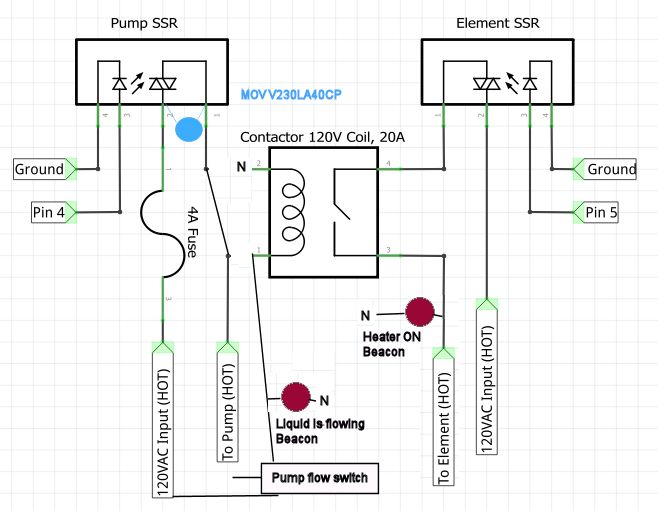
I've updated my schematic to use a contactor for the heating element. I wanted a fuse to protect my pump, I've tried to wire it in such a way that if the pump fuse blows that the element can't fire. Does this wiring look right? And more importantly, still safe?
Is that 1.4 amps for the pump the "run current" - or the "stall current"; if the "stall current" of that pump is larger than 4 amps, then your fuse might blow as soon as you applied power for the pump.
I still tend to wonder if you couldn't simplify this, again, by adding a second SSR. Have both switched by the Arduino; if you want to use a flow sensor (instead of a current sensor), route that as an input to the Arduino and have the Arduino monitor it. Keep the 120V mains fuse, but probably drop it to 15 amps (depending on the pump startup current, of course). If that fuse blows, the Arduino will shut off (provided you are using the USB port too), and the SSRs should be switched off as well.
Basically - let the microcontroller be the entire brains of the system; let the SSRs be the outputs, and use low-voltage switches or buttons (buttons likely - incorporate a character LCD for monitoring) for control/setup inputs, and the flow rate sensor for another input.
Here's what I got on the pump (more current than I had thought)
"Power 1/20 HP (.04 HP) .029 KW
Electrical 115V 50/60HZ
Non-Submersible
Motor AMP Rating - Full Load Amps (FLA)
Motor Only: 1.7 Amps
Motor and Pump: 1.9 Amps"
I suppose another ssr could simplify things, I wanted to maintain the ability to physically control the power flow if I needed to, maybe just an estop would be better.
[edit] would a mechanical relay be better for the pump? I assume they generate less heat, maybe that relay wouldn't require a heat sink. (The pump should pretty much always be on, not much switching)
Going the two relay route should I still physically tie the relays together so the element can not run with out the other? Like using a transistor on the relay inputs like so:
AND/OR should I put the ssr outputs in series?
Am I over complicating this?
(edit) If I put the 120v outputs in series then the pump relay will have the element current flowing through it and ill have to dissipate twice as much heat, correct?
Okay, this would seem to me to be the safest I can come up with:
However, if I do this is there significant advantage over my original approach? I could control the pump with my controller, I'm just wondering if I really want that (personal decision i guess)
OR just forget the contactor all together and hope no programming errors cause a dry fire?
Pumps can fail and/or liquid can be drained. I would use a flow switch as "permission" for the SSR to activate the heater. I also like indicator beacons, so someone can tell you over the phone what is, or is not, happening.
I also like a MOV across the SSR power terminals when switching an inductive load, such as a pump. It helps to suppress the voltage surge at turn OFF of the pump.