After assembling the version #2 bot and getting it to work, I tried my hand at version #3.
V3 is the 'shorty' version. Not just short (as in low height), but 'short-circuity' as well. Totally disappointed in the potentially nasty design flaw.
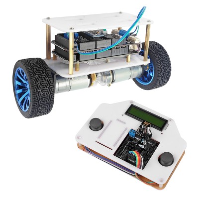
The balance bot from the web site image looks like this:
I put the bot together. The main things to look out for are: short-circuit issue; and orientation of the accelerometer (6050 mpu device) and the nrf24L01 wireless module. The instructions don't show users which pins are what. In the end, I used google 'images' to make sure I installed these small modules correctly (ie. correct pin slots). The general rule that I ended up using is - there are 3 blue trim-potentiometers. The wireless module and the mpu module need to be installed so that the wireless module board does NOT hang over the trim-pots, which means that the wireless board needs to be facing the 'other' direction (ie. not over the trim pots). The mpu board and the wireless board end up being side-by-side (next to each other).
The design flaw is in the set of solder bumps associated with one of the connectors (for one of the motors). Unsuspecting people (like myself) will assume that nobody is going to design and sell a commercially-available system that will have a whole set of solder bumps that will become short-circuited by a metal surface.
In this case, I was oblivious to the situation where mating the motor shield to the arduino 2560MEGA board will lead to 3 or 4 pins getting short-circuited by the shiny metal USB connector casing.
This not only meant 1 motor not working (when the unit became powered), but also possibly destroying something - components when powered-on.
After finding the issue, I needed to use a dremel grinder to grind down the solder bumps - to make the bumps shorter (to prevent the shorting). But the damage was already done. So I'm getting 12 V output to one motor, while the other motor is getting about 0.14 (yep....zero point one four) Volt.
Also, just like my V2 bot, the MPU (accelerometer/gyro) board was faulty. One of the axes kept reading 32768. So, once again (just like my version 2 bot experience, and having learned from it), I replaced the mpu with one of my own.....and the mpu issue was fixed.
But that doesn't fix a broken board. I might try my hand at tracking down what component/components is busted. It might even be the L298P surface mount chip has failed. I don't know at the moment. I decided to order another bot (of the same kind) to use as a reference in order to fix this one. This is hoping that the bot (to arrive) has 'working' parts.
Shown below is the problem area to look out for:

Actually, now that I think of it, the metallic hexagonal posts that come with the bot can be an issue as well, as one or more of them can cause short circuits too.
One final thing ...... physically connecting (mating) the motor shield to the arduino 2560MEGA board can be quite fiddly..... since existing pin positions and existing hole locations need to be just right in order to couple the two boards. The problem is..... not all pins and holes will be at those 'ideal' locations. So coupling the boards could first involve inserting a row of pins into your own individually-bought connectors.... to straighten them up and to pre-align them, and bending the female header sockets of the 2560MEGA to make them vertical. If lucky, they two boards can be coupled in a reasonably short amount of time, otherwise, could take 20 minutes of half an hour.


