Project 10 Zoetrope - nothing happens (at all)

Hello,

it's me again, I still have problems with the book's example. This time with project 10 about the H-bridge =(

I am basically in the same situation than ludossin in this topic: I made the book's circuit, but when I press the buttons, nothing happens.

So, I've decided to make a simpler circuit first.
I read this page http://itp.nyu.edu/physcomp/Labs/DCMotorControl and tried to reproduce this last circuit, and modified it a bit so that it basically runs the motor when you press the button (forgetting, for the moment, the idea of making it spin in both directions).

But here again, nothing happens. The motor doesn't spin at all. I tried to connect directly the 9v battery and the motor and it works, so I don't think the problem comes from them.

The only problem I can think about is that the first time I tried the circuit, I noticed afterwards that I had put the H-bridge the wrong way around, so absolutely ALL the H-bridge's pins were connected to the wrong wire...

What would you say ? Could it damage the H-bridge so bad it simply doesn't work anymore ? I'd like to know what's your opinion on this problem before going and buy a new H-bridge... I use the H-bridge shipped with the starter kit and it's the only one...

I attached a photograph of my circuit. It is actually meant to be the same than the picture, except I've put the switch on the other side.

Here's also my code, although it is so simple there's probably no problem with it:

const int switchPin = 2;
const int motorPin1 = 3;
const int motorPin2 = 4;
const int enablePin = 9;

int  buttonState;

void  setup() {
  Serial.begin(9600);
  
  pinMode(switchPin, INPUT);
  
  pinMode(motorPin1, OUTPUT);
  pinMode(motorPin2, OUTPUT);
  pinMode(enablePin, OUTPUT);
  
  digitalWrite(enablePin, LOW);
  digitalWrite(motorPin1, HIGH);
  digitalWrite(motorPin2, LOW);   
}

void  loop() {
  // read the state of the pushbutton value:
  buttonState = digitalRead(switchPin);

  // check if the pushbutton is pressed.
  // if it is, the buttonState is HIGH:
  if (buttonState == HIGH) {     
    // turn motor on:    
    Serial.println("Button pressed");
    digitalWrite(enablePin, HIGH);
  } 
  else {
    // turn motor off:
    Serial.println("Button not pressed");
    digitalWrite(enablePin, LOW);
  }  
}

I've put some serial prints to make some debug, but as I expected, pressing the button is detected, so the motor should turn on !

Thank you for your time and help :wink:

Hi,

Actually i also had problems with their instructions, although schematic and code were exactly the same. i started suspecting about damaged H bridge but with multimeter i realized that enablePin(output) was not getting power and so Hbridge was not getting power. i got rid of their code and started new one based on theirs step by step.First i wanted to make sure that H bridge was working and so i used this code:

const int onPin=5;
const int enablePin=9;
const int controlPin1=2;

void setup()
{
  pinMode(onPin,INPUT);
  pinMode(enablePin,OUTPUT); 
  pinMode(controlPin1,OUTPUT); 
  
  digitalWrite(controlPin1,LOW);
}

void loop()
{
  int motor=digitalRead(onPin);
  if(motor==HIGH)
  {
    digitalWrite(9,HIGH);
  }
  else
  {
    digitalWrite(9,LOW);
  }
}

And it worked, and then step by step i started adding toggle switch (lot cooler!! :b), direction of motor and finally speed and it the end all was working!! :smiley: try this code (its a bit messy to understand but its working), i think pins are the same but check it! i used the same schematic as they say ofcourse. hope i helped :slight_smile:

final code

const int onPin=5;
const int directionPin=4;
const int enablePin=9;
const int controlPin1=2;
const int controlPin2=3;
const int motorSpeed=A0;

int previousOnPin=0;
int previousDirectionPin=0;

int motorDirection=1;
int motorenable=0;


void setup()
{
  pinMode(onPin,INPUT);
  pinMode(motorSpeed,INPUT);
  pinMode(enablePin,OUTPUT); 
  pinMode(controlPin1,OUTPUT);
  pinMode(controlPin2,OUTPUT); 
  
}

void loop()
{
  int motor=digitalRead(onPin);
  delay(1);
  int motorDirectionState=digitalRead(directionPin);
  delay(1);
  int Speed=analogRead(motorSpeed)/4;
  
  if(motor != previousOnPin)
  { 
    if(motor==HIGH)
    {
      motorenable= !motorenable;
    }
  }
  
  if(motorDirectionState != previousDirectionPin)
  {
    if(motorDirectionState==HIGH)
    {
      motorDirection = !motorDirection;
    }
  }
  
  if(motorDirection==1)
  {
    digitalWrite(controlPin1,HIGH);
    digitalWrite(controlPin2,LOW);
  }
  else
  {
    digitalWrite(controlPin1,LOW);
    digitalWrite(controlPin2,HIGH);
  }
  
  if(motorenable==1)
  {
    analogWrite(enablePin,Speed);
  }
  else
  {
    analogWrite(enablePin,0);
  }
  previousDirectionPin=motorDirectionState;
  previousOnPin=motor;
}

Hi !
well basically we had the same idea (to try with a simpler circuit), but even your first example doesn't work for me (after replacing the pins numbers by mine of course) :frowning:

I tried a lot of things like using digitalWrite instead of analogWrite, without setting the enablePin to HIGH in the setup, setting only the first control pin to OUTPUT (like you did in your example), but nothing makes it work ! :0 I even tried to change the place of everything on the breadboard, but no luck...

By looking at the photograph, can you see any obvious error that I may be missing ? I also wish I had a multimeter, but where I work people aren't really into electronics, so wey lack even of the fundamental tools... =( I'm probably going to buy one tomorrow morning, I'll tell you what are the results...

hmm..very strange, that code is simple as you can get and worked for me. but if you get multimeter try to see if you have voltage in output pin 9 and also in 2 and 7 pins or just in one of them. these last two as to do with current direction.. they cant be both high or low or motor will not spin.if both are getting voltage ,schematic is like in arduino book and code is that one i showed you,you might consider damaged H bridge. cumps

So I've been measuring at some points on the circuit and it seems that the H-bridge is eventually broken :~

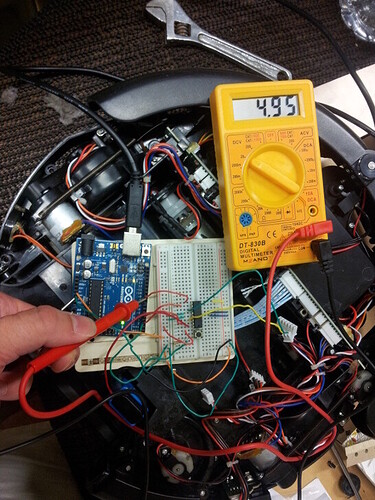
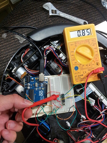
I've joined once again some photos of my measurements with the multimeter to be clearer but, as I understand the situation:

  • 5v power flows through pin 9 of the Arduino, which is suppposed to power pin 1 of the H bridge
  • 5v power flows through the wire between Arduino's pin 9 and H-bridge's pin 1
  • but in the meantime almost no power is measured through pin 1 of the H-bridge.

I haven't enough experience in H-bridges to be sure (it's the first time I use one !), but I think it means it's broken (why would it measure near to zero then ?). :slight_smile:

I should receive a new h-bridge on Monday, so we'll can figure out if the problem really comes from it (although if it doesn't solve the problem, I'll really be at a loss :sweat_smile: )

Hi,

Pin 1 one H bridge is the enable pin, or like the H bridge switch, when it gets voltage it starts running.So if you can measure voltage coming out from pin 9 of arduino 1st stage is checked. After what H bridge will do is compare voltage in pin 2 and 7 (they cant be both HIGH or LOW at same time). if pin 2 as voltage and 7 doesnt it will spin in one direction; if 2 doesnt have voltage and 7 does have it will spin in the other direction; if both pins have voltage or if both pins dont have voltage it will not spin at all. So this is your next step,check the voltage on both pins...

Hello, some news about my problem...
Yes, I know that if both digital pins for motor control are high or low, it stops the motor. So I checked the voltage of motor pins 1 and 2 on the Arduino and eventually the values are right : 0 for, say, motorpin1 if it's LOW, and 5v on the other, which is HIGH.

What I've found quite funny is that I measured the pins on the Hbridge and I had some surprises. For example I expected to find 0v and 5v on to the pins related to the Arduino's motorPins respectively LOW and HIGH, but instead, it measures about 1 volt or so on the two pins of the h-bridge connected to the motorPins.

So, to resume I measured:
0.85 volt on the hbridge pin connected to Arduino's enablePin (HIGH so measures 5v)
~1v on the hbridge pin connected to Arduino's motorPin2 which is LOW (so measures 0v
and ~1.42v on the hbridge pin connected to Arduino's motorPin1 (HIGH and measures 5v).

Apart from it, the 2 hbridge pins connected to the motor both measure 9v as expected.
I don't think so, but are such measurements normal with a h bridge? :~

PS: I measured on the old hbridge, the new one didn't arrive yet.

Hello again,

sorry for the double post, just to say that as soon as I started to use the new H-bridge, everything worked like a charm :slight_smile:

Thanks for the assistance anyway, it was really helpful.

Hello,

it seems I have a similar problem, but in my case the motor always turns full speed, completely ignoring the input on pin 1. Do you think I also have a faulty hbridge?

Edit:
It seems it was my own fault. The bridge had problems with keeping a good connection to the breadboard. And now the second cable of the motor tear :frowning: this is realy not my day

I had the same problem. The H bridge pins do not fit well into the starter kit bread board and without special effort you get only one side of the HB connected to the breadboard. With power wired into the same row as HBr pin 16, nothing happened. With the wire and pin 16 in the same hole, and a little more pushing the bridge down, everything worked fine.

As others have said already, I too can confirm the problem being the breadboard included with the starter kit (as of Dec. 2013). The H-Bridge does not fit very well into the breadboard: which either caused the circuit not to work at all or the motor spinning into only one direction when pushing the direction button (but not the on off button). A workaround for me was to move the H-Bridge to another position and slightly pushing it down with a finger, while testing the circuit.

Hi, thanks for the good answers.
The solution jad1715 posted worked for me pretty well.
When I first changed the code to the code posted by kaning it suddenly worked.
At least for a short while. But after turning the Potentiometer a while the motor stopped moving. I read the new code carefully. It turned out to be the same as the code from the book with different variable names.

Hello, i have the same Problem.

Hbridge sits in the breadbord just fine.
no matter what values i change, nothing happens.

this is my setup:
(attachment)

and this is the code I used to test it. (beside the original project code):

// 8,9,10

void setup(){
  pinMode(8,OUTPUT);
  pinMode(9,OUTPUT);
  pinMode(10,OUTPUT);
}
void loop(){
  digitalWrite(8,HIGH);
  digitalWrite(9,LOW);
  analogWrite(10,150);  
}

i have no idea what i'm doing wrong. please help me.

Hi !

-> sorry, but I just read the entire post and can't see anything 'wrong' on your setup

-> also, I have a [stupid ?] question to ask & some neat code to share, and I think it may help other people stuck on this topic ( ..), so here I go:

For the code part:

Instead of doing it the way the "Zoetrope" tutorial does, I prefered to have a push button as on/off toggle & a pot to select the direction as well as the speed:

// deduce the turntable motor direction & speed from the current pot value

// direction: from left to middle, direction is left, from middle to right, direction is right
turntable_motorDirection = turntablePotVal <= 511 ? 0 : 1;

// speed goes from 0 to 255  whatever the direction
//turntable_motorSpeed = turntable_motorDirection == 0 ? map(turntablePotVal+511, 511, 1023, 0, 1023)/4 : map(turntablePotVal, 511, 1023, 0, 1023)/4; // 1st version: minLeft maxLeftMinRight maxRight

turntable_motorSpeed = turntable_motorDirection == 0 ? map((511-turntablePotVal)+511, 511, 1023, 0, 1023)/4 : map(turntablePotVal, 511, 1023, 0, 1023)/4; // 2nd version: maxLeft minLeftMinRight maxRight

The 2nd version is prefered, as it uses one pot to go from 255->0 on the left & then directly goes on the right from speed 0->255 :wink:
I used the ternary operator here for clean & quick code while maintaining readability, but you could do the same with "if .. else .." statements ( .. ).

For the question part:

Is it possible that I may not be able to PWM the speed if the motor I'm using ( the Arduino starter kit DC motor ) requires much power than I provide it ? ( currently using 5v batteries instead of 9v in the tutorial .. ):

--> I checked, re-checked, & re-rechecked and my code for the direction & speed is working fine, but the motor only spins once arrived to the value 255 :confused: :expressionless: !

-> I 'll try as soon as I can to check what's going on, but I've ran several tests and all goes the same: directions OK, but motor only spinning while having the "motorSpeed" value to 255, not below ...

Thanks in advance for the anwser(s), I hope my code may be useful for some of us, and sorry for not finding your problem :confused:

IMtheSupervisor:
Hello, i have the same Problem.

Hbridge sits in the breadbord just fine.
no matter what values i change, nothing happens.

this is my setup:
(attachment)

and this is the code I used to test it. (beside the original project code):

// 8,9,10

void setup(){
  pinMode(8,OUTPUT);
  pinMode(9,OUTPUT);
  pinMode(10,OUTPUT);
}
void loop(){
  digitalWrite(8,HIGH);
  digitalWrite(9,LOW);
  analogWrite(10,150); 
}


i have no idea what i'm doing wrong. please help me.

It seems that the problem is that H-Bridge pin 16 is not connected to +5v line. In your picture pin 16 is located at row 12, column f on the breadboard.

I have no problem

I'm having similar problems with the zoetrope project.
In fact, not one of the projects has worked for me following the code in the Projects Book. Why is that?
I resort to just using the codes that preloaded in the arduino coding app.
How am I supposed to learn anything if none of the codes in the "text book" are correct. I'm an absolute beginner, so I have no ability to trouble shoot these problems. It has been so frustrating working my way through the book.
:frowning: