I've get the simple electret mic preamp to work using this (speaker is used for debug):
I use Arduino on a breadboard using ATmega8. My goal is to detect loud sounds like screams or short like handclaps by ADC. My ADC channel 0 is connected to pin 5 of LM386 (before capacitor to speaker).
Here are some questions:
I power amplifier from the same power supply (LM7805) as my MCU, my ATmega has all bypassing capacitors according to datasheet and Mike's pages. But I hear cracks in the speaker when leds are switched on a breadboard and I clearly hear my PWM frequency if I lower it to audible frequencies. When running from a battery the sound is clean. Is there any way to filter this, should I even consider this?
The output is biased to the half of supply votlage (around 2.5V), that's how LM386 works? It is a single supply op-amp, so it biases itself, right?
My ADC readings are inconsistent, I'm missing short sounds, it seems I need an envelope follower like this to "catch" short loud sounds:
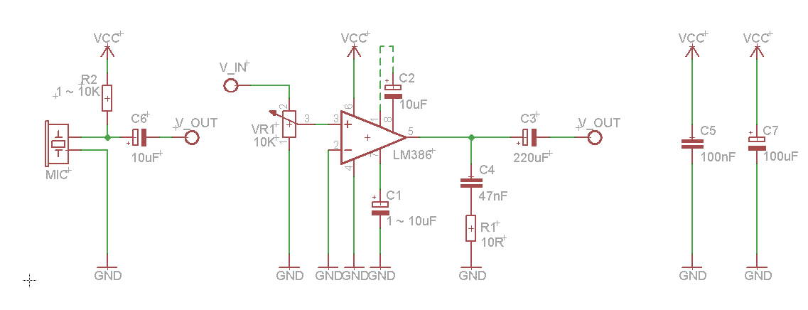
Over the last couple of days I've been battling with very similar problems. Attached is the schematic I've built - it's compiled from various sources
For me, adding the C5 and C7 capacitors was decisive in getting rid of the Arduino-induced noise. Place them as close to LM386's pin 6 as possible.
Here are some further ideas:
Add the bypass capacitor at pin 7; Add the R1 + C4 at the output.
Keep all components as close to the IC as possible.
If working on a breadbord, don't overextend the supply and ground rails. People say they may act as an antenna and pick up random noise.
Re your other questions:
Yes, the output voltage at pin 5 is biased to ~2.5V
To get better mic sensitivity, try tweaking the value of the resistor between Vcc and Mic+ (R2). This article Powering microphones suggests using a 2K2 resistor, but 10K worked out much better for me.
P.S. Here are the exact component values I'm using: R2=10K, no VR1, C1=10uF, no C2
Thank you for the detailed responses. In case anybody interested, here are results:
My schematics is as following:
Details:
I haven't use "gain" capacitor (marked as C2 on DimKo's schematics)
I use R2=10K
The actual problem with my readings was in a software, my readings were slow and I missed short sounds
My circuit run without bypass capacitors on LM386 (because my target was to detect only loud sound), but I've tried adding them and they reduce noise from PWM and switching pins significally