Hello everyone, I finally got a chance to 'finish' this more or less. I'll use it for my transmission fans and after a long time if it proves to be reliable I might do more with it.
I wound up using the 5v arduino output which I believe supports up to around 50mA. I put a 680Ohm resistor inline so the max current should be near 8mA "at worst". I have generic code from online that I modified to calibrate to my exact temperature sensor, which is a generic 1/8" NPT thermisistor from "ebay" (they sell all over the place)
Here are the posted values for generic sensor I am using:
37.8℃ — 450 ±45 Ohm
104.4℃ — 46.6 ±2.3 Ohm
100℉ — 450.0 ±45.0 Ohm
150℉ — 158.20 ±15.82 Ohm
200℉ — 64.30 ±6.43 Ohm
250℉ — 29.25 ±2.93 Ohm
300℉ — 14.96 ±2.25 Ohm
Here is the code now,
#define RT0 450 // Ω
#define B 3450 // K (changed this value to correct for my sensors)
//--------------------------------------
//perfectly matched to my sensors verified 3x of them (one read 2*C higher tho)
#define VCC 4.8
#define R 680
//Variables
float RT, VR, ln, TX, T0, VRT;
void setup() {
Serial.begin(9600);
T0 = 37.8 + 273.15; //Temperature T0 from datasheet, conversion from Celsius to kelvin
}
void loop() {
VRT = analogRead(A0); //Acquisition analog value of VRT
Serial.println(VRT);
VRT = (5.00 / 1023.00) * VRT; //Conversion to voltage
VR = VCC - VRT;
RT = VRT / (VR / R); //Resistance of RT
ln = log(RT / RT0);
TX = (1 / ((ln / B) + (1 / T0))); //Temperature from thermistor
TX = TX - 273.15; //Conversion to Celsius
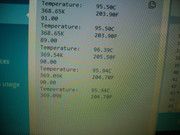
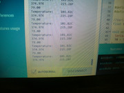
Serial.print("Temperature:");
Serial.print("\t");
Serial.print(TX);
Serial.print("C\t\t");
Serial.print(TX + 273.15); //Conversion to Kelvin
Serial.print("K\t\t");
Serial.print((TX * 1.8) + 32); //Conversion to Fahrenheit
Serial.println("F");
delay(1500);
}
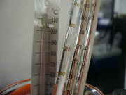
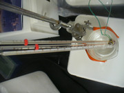
Pictures!!

So anyways. Now that I've got it reading the sensor right, I am going to program some SWITCHING on and off for the fans. And a little LED to let me know its on or off.
--> I still have many questions
-
Is there anything I can do to further reduce the current drawn off the 5V arduino pin when this thing heats up fully? I Notice the higher my resistor goes, the less ADC resolution seems to be (fewer ADC counts due to lower voltage at A0 pin), so I chose a value which gave a reasonable resolution but it still only uses around half of the ADC scale (500 to ~100).
-
It would be nice to be able to adjust the fan ON and OFF switching point with a dial or something in real time. Is there any way to wire an additional variable resistor to control the fan ON and OFF points? I know I can add resistance inline to lower the ADC I guess this would simulate a higher temperature... but how can I adjust it DOWN also? IS there a simpler way I am not seeing without playing the resistance to ground or 5v?
-
I will a digital out pin and a transistor to switch a fan relay. And another digital pin for an LED I guess.
Is there anything cool I can also do I am not seeing?
basically just looking for more control inputs, more interesting methods, and to reduce any wasted current flow. Like, there must be a way to accomplish this without wasting 8mA? Can a transistor or amplifier somehow be used to get the same resolution at a much lower current flow? I should experiment.....
