Thanks to Crossroads for putting me up to wire-wrapping as an alternative way of putting projects together!
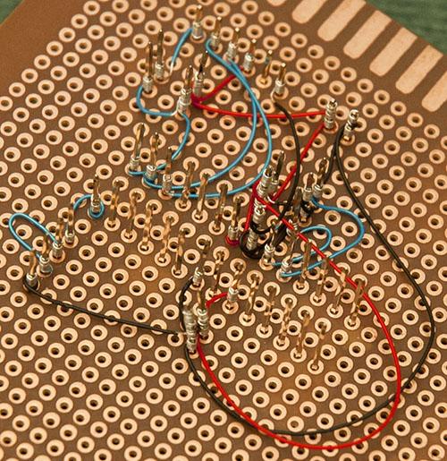
Here is my wire-wrapped (minimal) board:
There is a 16 MHz resonator, a couple of decoupling capacitors, a 10K pullup for the reset line, and a 0.1uF capacitor for the reset activation. Also an LED and limiting resistor. Programming is via the 6 FTDI pins, and the power pins are next to that.
WSU-30 wire-wrapping tool, as recommended by Crossroads
Wire-wrapping wire in three colours
Single-inline wire-wrap sockets for the capacitors, etc.
Dual-inline sockets (2 x 14 pin) similar to the one in the photo
Extra-long pin header strip for the FTDI connection
More information about wire-wrapping:
I know it's a bit of a mess, but this was my first attempt at wire-wrapping. It works, though. The "blink" sketch uploaded and worked (I had to change it to use A5 because I got the pins a bit mixed up when I was wiring up the LED).
This demonstrates that you can get an Atmega328 working, and programmable from the Arduino IDE, with a minimal amount of components, and not even needing power (for soldering anyway).
There is no voltage regulator, that could be added without too much extra trouble.
I'd noticed Crossroads' wirewrapped scoreboard project and was taken back a few decades by it... wirewrapping always had a kind of "artistic" appeal to me that soldering doesn't. There's almost a whole zen thing to strip, twist, clip, repeat.. and if you get distracted, you don't give yourself blisters or set the cat on fire...
Overall, doesn't it get expensive though? I've always viewed it as doing calligraphy versus scribbling with a crayon, an aesthetic thing mainly. I did a little YEARS ago, and haven't given it much consideration since I "returned" to hobby electronics. Is there more to it?
Nice work. I've used wire-wrap in the past, but now mostly use wire-wrap wire but solder point to point on perf or proto boards. When I did use to wire-wrap I would still solder the pins/posts at the pad holes to give the sockets and connectors (at least the corner or end pins) for more mechanical stablity and strength.
focalist:
Overall, doesn't it get expensive though? I've always viewed it as doing calligraphy versus scribbling with a crayon, an aesthetic thing mainly. I did a little YEARS ago, and haven't given it much consideration since I "returned" to hobby electronics. Is there more to it?
Once you've got the tool (around $US 35) your only real expense is the wire (around $US 10 for 100 feet). And the wire-wrap sockets I suppose, as required.
As for the advantages, well Crossroads might be able to comment on why he uses it.
For me, I found that, whilst it was a bit slower than soldering, it had the following advantages:
Using the board without any pre-made strips I could just place things where I wanted.
You can wrap up to 3 lots of wires on one post. As you know, soldering multiple wires to one point can be fiddly as two lift off while you try to solder in the third.
The components were just pushed into the sockets. So if you change your mind about a resistor or capacitor value, you just lift it out and replace it. Soldered-in parts can be easily destroyed as you try to unsolder both pins simultaneously, pull them out and not burn yourself.
If you make a mistake you just unwrap (other end of the tool) and replace the wire.
According to Wikipedia, the tool forces the wire against the post with tons of pressure. The wire bites into the corners, making something like 20 redundant connection points (you only really need one).
Correctly done, it should be more reliable than solder because you don't get dry joints. Nor do you overheat your parts.
If you already have a circuit board, I think it would be somewhat slower than just quickly soldering on a whole lot of points. But for a prototype or one-off, you get the flexibility of making changes later on. Plus all those posts make convenient test points for your meter or oscilloscope probe.
retrolefty:
When I did use to wire-wrap I would still solder the pins/posts at the pad holes to give the sockets and connectors (at least the corner or end pins) for more mechanical stablity and strength.
Good idea, and that was what Crossroads recommended. I didn't in the end because I was really just testing the idea. The parts do wobble a bit (although the wrap on the other side tends to keep them in place). Also on this particular board I had to push quite hard to get the sockets to go through, so that gave it a fair bit of mechanical strength.
A dab of solder at each end of the strips would no doubt make it much more rigid. And that probably helps too, because if the posts move the wire-wrap joins might be compromised.
I like wire-wrap myself, but I haven't done it in years; I recently bought a large spool of wire from my favorite local haunt (Apache Reclamation and Electronics) because it is useful for other things, and it had been sitting there for years (since the last time I purchased many feet from it 15 years ago). I decided I would buy the entire spool (I think I was charged $15.00 or something).
The thing I didn't like about wire-wrapping was the cost of the sockets and such - even surplus they are much more expensive than standard solderable parts. Also, I didn't like the fact that on a complex circuit, if you made a mistake and didn't catch it in time (and you didn't use the proper wire-wrapping approach) - you might have to take more layers off from a pin than you expect, and on a dense layout, that can be maddening.
About that: Yes - there is are methods to wire-wrapping; I can give any specifics, but I have read about how to properly wire-wrap in such a manner so that if you do make a mistake (or find you have to alter something later) on a complex circuit, there are ways to wire it so that you don't have to take more than one or two layers off the post. On extremely complex layouts, this kind of practice is necessary.
cr0sh:
I have read about how to properly wire-wrap in such a manner so that if you do make a mistake (or find you have to alter something later) on a complex circuit, there are ways to wire it so that you don't have to take more than one or two layers off the post.
What I read was that you make sure that you reverse the order. Eg. the top wire on one post goes to the bottom of the other post. That way you have a maximum of two wires to move out of the way.
I have been inspired by these posts on wire wrap, so I ordered a tool, and it just arrived. I have done a couple practice wraps, and it is cool! Now I have to figure out a real project...
You guys are doing a great job of discussing this
Depending on how much time I felt like spending, I have both trimmed miswired connections and carefulluy unwrapped around a post, or just cut the wire next to the post and just left it there.
Posts come in differentl lengths - I have used 3-level and 5-level posts. 5-level is good for power connections, 3-level is good for just about everything else.
You can buy sockets, or buy lenghts of socket strips and make your own sockets - that't what I've been doing to get 2 & 3 contact for resistors & stuff, or wider sockets for plugging pro-minis into, which are wider than standard wide DIP sockets.
I have bought a bunch of sockets here
And you can wirewrap to straight feed thru pins, and also to the back of LEDs directly!
Not shown is the LED and resistor - that was only there anyway to prove it worked. I also added a reset switch to the circuit which is not on the original board.
Also not shown are the two pins I used for +5V and Ground. They are available anyway on the FTDI connector, and it is pretty obvious where they go.
Nick said "on this particular board I had to push quite hard to get the sockets to go through"
If you look at the board used, you can see that the holes are not centered in the pads, they are all over the place.
Any parts would have been difficult to install.
I have been using Velleman ecs1/2 and ecs1-H, better hole quality so no installation problems like that.
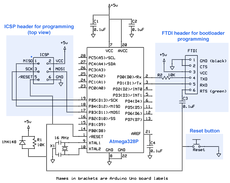
The ExpressSCH didn't have an Atmega328 so I took another 28-pin model and renamed it. Unfortunately some of the pin names were wrong.
I have amended the graphic, and moved the pins around a bit so they are more in numeric sequence. Most pins are now labelled with the "Arduino" pin in brackets (eg. 25: PC2 (A2)). That is pin 25 on the chip is PC2 (bit 2 of the PC register) and is brought out to the pin labelled A2 on the Arduino board.
Wires that directly cross on the schematic are not connected.