I have got this circuit with the help of stack exchange that uses a peak detector to let me sample extremely fast without the Arduino needing to sample quickly at all (that is at least what I understood. Sorry I have been using the arduino for a while but havn't done large projects like this without much of a guide before)
This is the schematic I was given. I put this onto a breadboard with an arduino and a
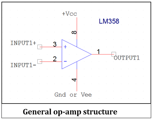
I am using a Lm358, and I didn't think that was right but the person on stack exchange seemed very knowledgeable and helpful so I used his schematic. My project is to have many unidirectional microphones in a semi circle (9) to detect the direction of the loudest noise. Any ideas are appreciated, thanks.
EDIT:
His schematic is correct I am just reading it wrong
The schematic tells you to connect Vout- to the V-, gnd, Vss, or Vee of the op-amp, and Vout+ to V+, Vdd, or Vcc of the op-amp and the resistor to the microphone. The schematic seems correct, as far as I can tell.
Okay I understand, I am just reading it wrong. I will connected out- directly too pin 4 and out+ directly too pin 8. I am still reading 0. Do you think I have created the circuit on the breadboard wrong? Thanks
It's hard to tell what's going on on your breadboard.
Could you upload a new picture that clearly shows all connections?
What's the purpose of the capacitors on the inputs? Are you reading the correct pin in your code?
Maybe you blew up te regulator. Try measuring its output voltage with a DMM, or use an LED+ series resistor to see if it still provides power.
And the stack exchange guy said I should put 'decoupling capacitors (100nf)' on the power pins. I only just realised they are not the power pins. Shall I remove them entirly or just move them to v- and v+
Many Thanks,
Thomas
(as a side note thank you very much for reading through the breadboard from a picture, I would never be able to do that)
You forgot to connect the ground, and you didn't connect the mic to Vout+ through R4. The wire to your Arduino is connected to ground instead of the output of the circuit (through the 1kΩ resistor).
Yes, it is the original schematic unless I have made a mistake:
Does the polarity of the electret microphone matter?
EDIT:
I read through the schematic one more time and re-positioned some components, and now I am pretty sure that the schematic is what I have on the breadboard. The analog read now starts at 0 slowly rises to around 1023 then drops again. If these results point to the schematic being wrong, Ill use a bigger breadboard and remake the whole thing. Thanks
Like This:
And the amplifier only has a gain of 10 so you might get small readings unless the sound is very loud.
If you appear to be reading "something" with loud sounds, try increasing R3 to 100K.
You can also switch to the optional 1.1V ADC reference to compensate for low signal levels.
Are all of the grounds tied together?
Are the + & - terminals on the electret mic clearly marked and correctly connected? (The audio signal is AC, so polarity doesn't matter but the power to an electret mic does matter.)
Do you have a multimeter? If not, it's probably time to get one...
Make sure you have the positive & negative power supplies to the op-amp.
My project is to have many unidirectional microphones in a semi circle (9) to detect the direction of the loudest noise. Any ideas are appreciated, thanks.
You'll need a significant (percentage-wise) distance-difference to get a significant difference in loudness. And indoors, it may not work at all because reflections tend to even-out loudness throughout the room.
With no signal the output of the op-amp (before the diode) should be resting at about 0.6V (because of the diode in the feedback loop). The other side of the diode (and the Arduino's analog input) should be reading about zero. We know it's not positive because the Arduino is reading zero, but it might be negative.
The circuit is simply wrong, I a tempted to say go find a proper one, but basically the inverting and non-inverting inputs are swapped over, so the opamp is a comparator with a vast amount of hysteresis. There is far too little
gain possible with those resistors too.
The circuit is simply wrong, I a tempted to say go find a proper one, but basically the inverting and non-inverting inputs are swapped over, so the opamp is a comparator with a vast amount of hysteresis.
Good catch!!! ...I did not notice that.
Swap the + &- inputs to the op-amp (so you get negative feedback to control the gain) and increase the feedback resistor R3 for more gain, and it should work.
Or, SparkFun publishes the [u]schematic[/u] for their board if you want to see a another version/option. (You can leave-out the buffer since the Arduino is has a high impedance input, and you can leave-out the Schmitt trigger since you only want an analog output.
I've made amplifiers and I've made peak detectors but I've never made an all-in-one circuit with an electret mic. ..If it was me, I'd buy the boards. The cost is going to be about the same and you don't have the hassle of building, testing, and debugging and you get a nicely-assembled printed circuit board without having to design your own board. (Although, I would prefer a board with a gain-adjustment pot.)
Thank you very much everyone, and to DVDdoug, I swapped the two inputs and am getting the same results... I think I have probably ruined the circuit somewhere when swapping around connections. The reason I want my own board is so I can have all 9 of these around the outside on one PCB rather then a lot of them on top of each other, which I feel in the long run will make it cheaper. Since I am remaking the whole circuit, should I go with the sparkfun schematic or the one I have listed below? Many Thanks,
Thomas