Rotary encoder midi!

Hi!
I would like to make a midi device Rotary encoder. I have added an Arduino UNO board. I would like you to deal with Ableton and Traktor and other DAW software.
I found a seemingly good code, but teensy board was written and gives a lot of mistakes. I have an Arduino Uno board and I want to use.
Can you help me to know what the code change that?

#include <Encoder.h>

Encoder enc_one(2, 3);
int value; 

long enc_one_previous  = -999;
byte button_previous; 

void setup() {
 pinMode(23, INPUT_PULLUP); 
}


void loop() {
 value = enc_one.read();
 if(value > 127) {    enc_one.write(127);   }
 else if(value < 0) {    enc_one.write(0);  } 
 
 value = constrain(value, 0, 127);
 if (value != enc_one_previous) {    enc_one_previous = value;    usbMIDI.sendControlChange(1, value, 1);  }
 
 value = digitalRead(23); 
 if(value != button_previous) {    button_previous = value;    usbMIDI.sendControlChange(2, (1 - value) * 127, 1);    delay(3);  }
}

The Uno doesn't support MIDI over USB like a Teensy does. You can get it to work by flashing custom firmware to the on-board ATmega16U2. I explained everything in this article: Custom Arduino MIDI Controller. You can find example sketches as well, or you could check the source files of the library, to see how I implemented it.

The MIDI_Controller library (download it from the link above) includes this very simple example:

#include <MIDI_controller.h>

const static byte Channel = 1;
const static byte Controller = 0x14;

RotaryEncoder enc(2,3,Controller,Channel,1,JOG,POS1_NEG127); // Create a new member of the class 'RotaryEncoder', called 'enc', on pin 2 and 3, controller number 0x14, on channel1, no change in speed (speed is multiplied by 1), it's used as a Jog wheel, and the mode is set to POS1_NEG127.

void setup(){
  setupMidi(13, 10); // Setup the MIDI communication, with an LED on pin 13, and a delay of 10ms after every message.
}

void loop(){
  enc.refresh();
}

Pieter

I use Moco Dual technologie. I wish you the rotary encoder would have values between 1 and 127.
But I have not found a solution. Can someone help me on this?

Did you read steps 10 & 12 ? A rotary encoder is a relative positioning device, and there's at least 3 ways to convert its movement to relative MIDI messages (between 0 - 127), the library supports three different modes, just experiment what works with your DAW.
If you just want a knob that goes from 0 - 127, depending on the absolute position, you need a potentiometer.

Pieter

I need rotary encoder because it is push button! :slight_smile:
I tried a variety of code already, but none of them worked perfectly well. :frowning:

The library said midi give these mistakes:

C:\Users\...\Documents\Arduino\libraries\MIDI_controller\Analog.cpp: In constructor 'Analog::Analog(byte, byte, byte, byte)':

C:\Users\...\Documents\Arduino\libraries\MIDI_controller\Analog.cpp:11:6: error: 'dPin' was not declared in this scope

   if(dPin < A0 || dPin > A5){ //If the user enters an invalid pin number. 

      ^

exit status 1
Error compiling for board Arduino/Genuino Uno.

My bad, I had made some changes to the code for the Arduino Leonardo and forgot to change the code for the Uno, resulting in different variable names (dPin should be p). I uploaded a new version: delete the old library and download + install the new version.
I tried it and it works just fine now.

Pieter

Excuse me, but now I can not find the MIDI_controller.zip website. Can you help that I download from?
Thanks!

bakonyip95:
Excuse me, but now I can not find the MIDI_controller.zip website. Can you help that I download from?
Thanks!

Here ya go: http://www.instructables.com/id/Custom-Arduino-MIDI-Controller/step13/The-Library/

Thanks, managed to write on, but does not communicate with MIDI port. I use DualMoco USB firmware, which is to usb midi device. How can I solve that information to send MIDI port on the device?

I changed the baud to 115200 to test it, and forgot to change it back to 31250. That should be fixed now, so I hope it'll work after reinstalling the library.
Sorry about that.

Pieter

So you have to communicate, but it is the next problem:
It works with the shooting, but wherever rotated only increases the value never decreases. Why is this possible?

You have to select the right settings in your DAW, for example in Reaper, you have to select the relative CC mode:
Reaper_Rotary_Encoder.png

It is selected, unfortunately, many do not have the option Tractor

Traktor does support it, read the instructions here.

The MIDI controller library allows you to change the encoder mode as well:

RotaryEncoder enc(2,3,Controller,Channel,1,JOG,POS1_NEG127); // corresponds to Traktor encoder mode "7Fh/01h"

RotaryEncoder enc(2,3,Controller,Channel,1,JOG,ADD_64); // corresponds to Traktor encoder mode "3Fh/41h"

ADD_64
First mode for relative MIDI messages. This is probably the simplest one. This basically maps 0 to 64 (which is 128/2). For example, if I want to send -1, I add 64, = 63 and I send it. If I want to send +1, I also add 64, = 65. If I just send 64, the computer will do nothing, because it knows it's a displacement of 0. (On the computer side, they just subtract 64, and you can use the result like nothing ever happened.)

SIGN_BIT
Second mode for relative MIDI messages. On computers, signed values are mostly saved with a sign bit. The sign bit is the most significant bit. When it's 0, the number defined by the other bits is positive, when it's 1, the number is negative. In a MIDI message, this is bit 6 (the 7th bit, since it's 0 based). For example: +4 would be 0b00000100, and -4 would be 0b01000100.

POS1_NEG127
Third mode for relative MIDI messages. Define +1 as 1, and -1 as 127. We can continue this: +2 = 2, and -2 = 126, etc. until +63 = 63, and -63 = 65.

Side note: It's better to use the NORMAL_ENCODER option: it will send 1 message per click, instead of 4, this will be smoother:

RotaryEncoder enc(2,3,Controller,Channel,1,NORMAL_ENCODER,POS1_NEG127);

RotaryEncoder(byte pin1, byte pin2, byte controller, byte channel, int speedMultiply, byte pulsesPerStep, byte mode);

pulsesPerStep is the number of pulses the encoder outputs when you turn it one step or click. On a normal rotary encoder, this is 4. When you set it to 4, it will change 1 unit in your software per click you turn, instead of 4. This is mostly more logical. For jog wheels however, you may want to set it to 1, to take advantage of the full resolution of the wheel. Use 'NORMAL_ENCODER' or 'JOG' as argument.
[...]
NORMAL_ENCODER
set pulsesPerStep to 4, for normal rotary encoders.

JOG
set pulsesPerStep to 1, for jog wheels.

If you really want an absolute mode, just let me know, and I'll add it to the library.

Pieter

I understand, but apparently everything is set correctly, no matter where they wrap only increase the value never decreases and then reaches a maximum and no more ...
Why is that?

My apologies for the late reply.

I installed the demo version of Traktor, and it works just fine for me with these settings:

This is the code I'm using:

#include <MIDI_controller.h>

const static byte Channel = 1;
const static byte Controller = 0x14;

RotaryEncoder enc(2, 3, Controller, 1, 1, NORMAL_ENCODER, POS1_NEG127);

void setup() {
  setupMidi(13, 10); // Setup the MIDI communication, with an LED on pin 13, and a delay of 10ms after every message.
  delay(1000); // Wait a second...
}

void loop() {
  enc.refresh();
}

Are you sure that you have your encoder wired up correctly? Did you connect one of the data wires to ground instead of the common wire?

Pieter

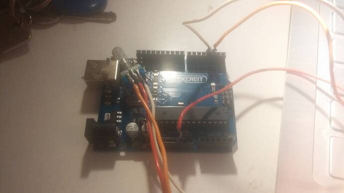
I connected my way:

Try swapping the orange and red wire, then try swapping the orange and the white wire.
Did you read the directions for connecting the encoder, in step 11?

If you don't have the datasheet, try connection it to two LEDs (+resistor ! ). Connect the anodes of the LEDs to the +5V of an Arduino or other power supply, connect their cathodes via two resistors to two of the pins of the encoder, and connect the third pin to the ground of the Arduino. Now slowly turn the encoder. LED 1 should light up first, then LED2, then LED1 should go out, and finally LED2 should go out. The order of the LEDs lighting up should be like this: (○ ○) (● ○) (● ●) (○ ●) (○ ○). If this is the case, the common, or C pin of the encoder is the one you connected to the ground. If this is not the case, and the LEDs go on or off simultaneously, swap two wires and try again. (Don't worry, you will eventually find the right pin, there are only 3 possibilities.) The order of pin A and B doesn't matter.

Pieter

I tried all three options. Only One of Them Both communicates with the two directions, but It also Increases the value of ...
It has such an encoder:

EC11 Rotary encoder