Hey Ive got a strange problem. Ive made a homebrew Motor controller that basically consists of a mosfet that switches a relais these both power the motor. When I turn it on without anything attached to it it works just fine and theres voltage at the output but if i connect a load to the circuit output, the arduino just stops switching. There isnt any voltage on the pin and it doesnt start working again until I reconnect the power supply. Im using an Arduino Nano heres my code. Help is greatly appreciated.
void setup() {
pinMode(12,OUTPUT); //individual pins of the 2channel motorcontroller
pinMode(11,OUTPUT);
pinMode(8,OUTPUT);
pinMode(9,OUTPUT);
digitalWrite(12,HIGH);
}
void loop() {
// put your main code here, to run repeatedly:
digitalWrite(12,HIGH);
delay(2000);
digitalWrite(12,LOW);
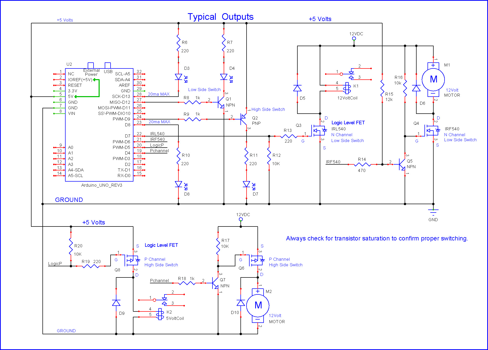
I think if you supplied at least a rude schematic and some specifications (which MOSFET? resistor values? etc.) you may be less likely to be insulted by a crusty old-timer and more likely to get a useful response.
Ok Im using a IRL234N with a pulldown resistor. The diagramm shows half a channel there is just 2 of those things for each channel and four for the whole controller.
Yes I know. But its not the overall concept because Ive tried it before and have built a couple of projects with this circuit. I think maybe because of the relais they need a higher voltage to switch than usual.
The power supply is fine its powered by a Lab bench power supply.
The arduino is powered by an L7806 voltage regulator.
Everything has a common ground.
I know the concept works because Ive tried it before. I think just need a way how to decouple the transistor from the Relais in a way where it isnt affected by the induction that occurs when it is under load. Is that even possible?
Hi,
You all should be shot;
Look at the diagram;
How is that circuit supposed to work?
With no load the relay will work.
Add a load and the load current will flow through the contacts AND Q1!!!!!
“You all should be shot;” . . .
“How is that circuit supposed to work?
With no load the relay will work.
Add a load and the load current will flow through the contacts AND Q1!!!!!”
Said the cct. was wrong back in #7.
“BTW, your drawing shown in my post #3 is not correct.
Compare it to my drawing for K1.”
Hi,
The Op is taking notice but not seeing the cause if his/her problem as we keep pointing out.
So hopefully editing the diagram he/she seems to understand, may be "clearer".
A nice picture of a hand drawn, complete diagram would be the best solution.
The diagram being drawn by reverse engineering what to OP has constructed, please.
Hey you guys
I thank you for your help. And yes your right id probably deserve to get shot. Because the problem was just rushing and not thinking about it and an absolute shit solder job. What I basically did was just redo the whole thing because it looked absolutely abysmal. Also I added a few diodes on the outputs because there was a short there I didnt see when I planned the thing. Who would have known if you do shit properly it actually works...