Hello, I did last time in the Eagle program 4 years ago. I would like to make a PCB board which is very simple, there will be: LCD display 20x4, I2C converter, RFID reader RC522, Arduino Nano, or future AtMega328. I downloaded various parts that are not given in standard libraries. The LCD display may seem to be a must, however?
Wiring:

It would be enough for the I2C converter to make that design. On the RFID reader I found it to be quite different (mirrored). Here is the second question .. When I draw it, does it mean I look at these modules from above? I'm a little overwhelmed ...
I came out of this design (RFID reader I mirrored inverted) grid I set to 1.27mm. Has anyone managed to dismantle, position, or see a problem somehow?
PCB:
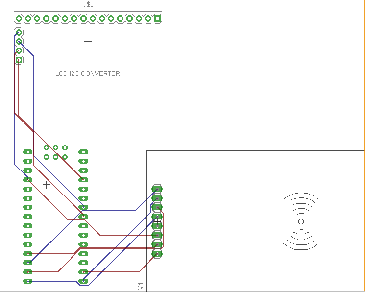
It should only be a single board as a prototype and later I want to replace the Nano for the AtMega328 with an internal oscillator. The principle is just reading a few keys (22pcs) and measuring time (stopwatch).
And I'm going to display it .. I imagine so that the transducer there from the back of the board and display front .. It should work this way, or I would get those I2C pins from the converter pulled on some pins on the PCB and they would go to A4 A5 ..