I have a problem with the stability of the read value of the ADCs of my Due. I wanted to check how stable the valuesare I read using the ADC ports. To do this I used a voltage divider between 3v3 and GND to get a reading somewhere in the middle of the voltage range, a condensator in parallel to it to reduce the noise on the supply voltage and a passive low pass filter to reduce the noise even further before I connect the signal to an ADC pin. See attached image.
In the sketch I did nothing but setting the analogreadresoultion to 12 bit, and reading the analog value and posting it to the serial port using analogread and serial.print.
Result: The read value varies around 10 units so basically 3 bits of the analog read resoliution are wasted on noise.
As I plan to use at least 11 of the 12 bits of ADC resolution I need to improve this. I tried different ADC ports, varied resistor and capacitor values and implemented some delay (up to 1s) between the analog reads with more or less no change.
The question is what is influencing the read value. I see 3 possible sources.
First of all I wired all of this on a little test board with some wires from and to the Due board. This could simply pick up some noise. I will solder a test board but this will take me some days as I need to get some parts.
Second possibility is that the supply voltage and/or the derived analog reference voltage is not stable enough. Can somebody give me some guidance how to check this? I would prefer not to modify the DUE board itself but at last for the analog reference voltage that would be necessary.
Third possilibilty is that I got a faulty or a clone board of insufficient quality. The board looks quite ok and like the original ones but I didn't buy it in an official store. Therefore it might be an low quality clone. Is there any possiblity to check this without buying another DUE?
Can anybody state some expierence with the DUEs ADCs? Is the performance I measured typicall?
I'm surprised your readings are actually this stable. The signal connected to the ADC should be buffered or have low impedance, preferably less than 10K. In the datasheet (pg 1419), see Table 46-35 Source impedance values.
thanks for the reply. As far as I understood it the limit for the impedance comes from the fact that the there is some input capacity for the ADC and you need some current in order to get the voltage to reach the set voltage fast enough. And it is especially necessary if you switch ADC channels, as there is only one ADC that is multiplexed.
As i only use one analog input and I don't see a voltage drift but noise I don't think the impedance is an issue. But I will check if this is an issue by adding an OpAmp as a voltage follower in between my circuit and the ADC input.
I've found that all inputs that I don't apply a band-stop 45-55 Hz filter to will show very noticable line noise. Even on circuits that are noise filtered before I connect them to the Due (e.g., the Olimex EKG-EMG shields supposedly have a filter circuit built in).
It doesn't seem to matter if it's all running off battery or if I eliminate all power lines on the table - the 50 Hz vibe is literally everywhere.
Yes, the Due analog section is pretty crap. The DAC is worse, BTW, it seems to have sparkle
codes that deviate 20+ counts IIRC. And it doesn't do rail-to-rail. I suspect the poor performance
is partly the chip and partly the layout of the board - the switchmode supply is too close to the sensitive
analog signals perhaps.
Another thing you could do is to use a external voltage reference IC, I have soldered a REF2030 to a SO8 adapter board that sits in D13, GND, Vref. So D13 powers the IC, if using a external reference one needs to re-solder a jumper on the board that ties the supply voltage to the Vref pin.
But if the ADC is used to read the supply voltage maybe it won't help much if the noise is still in the supply voltage?
I have made a layout for a tiny little PCB that should be able to be soldered into the due much more closely to the SAM so as to not have such a long way for the reference IC to connect to the chip, its kind of sketchy but it will work if one would want a proper reference voltage.
I've tried with an external reference voltage myself (from an LM4040, for testing), and I still observed the 50 Hz noise.
For comparison, I also connected an ADS1115 via I²C, and - even with everything operating on battery! - was able to spot the 50 Hz noise there.
So, yeah, the stuff simply is so sensitive that the 50 Hz noise from the environment is being picked up. I doubt the Due construction is to be blamed for that.
Frankly, I was amazed, I (as a software guy) always thought "electro smog" was somet new-agey hippie crap, until it showed up in my own measurements
void loop() {
total = total + analogRead(A0) - val;
val = total / 32;
}
Ok, it took me some minutes but I think I got it. It is basically a digital low pass filter. The noise is reduced by square root of 32 (as expected for averaging). But it will slow down the measurement as it takes 5 to 10 times 32 to get a stable value. As long as the measurement value is changing very slow this is a good solution. So definitely worth remembering.
Thanks
Daniel
Microzod:
Another thing you could do is to use a external voltage reference IC, I have soldered a REF2030 to a SO8 adapter board that sits in D13, GND, Vref. So D13 powers the IC, if using a external reference one needs to re-solder a jumper on the board that ties the supply voltage to the Vref pin.
I was thinking about something like this myself. But as the SAM... is powered by a most probably noise 3v3 voltage I am not sure how much this will help. It might be necessary to add some stabilization to the 3v3 voltage itself. Could you share some experience with this?
Microzod:
But if the ADC is used to read the supply voltage maybe it won't help much if the noise is still in the supply voltage?
I was just using this setup to play around with the ADC and to get some feeling how I can use the ADC. What can I expect and what is the effort to achieve this.
Microzod:
I have made a layout for a tiny little PCB that should be able to be soldered into the due much more closely to the SAM so as to not have such a long way for the reference IC to connect to the chip, its kind of sketchy but it will work if one would want a proper reference voltage.
Could you share the design? I would be interested in that.
l-mb:
So, yeah, the stuff simply is so sensitive that the 50 Hz noise from the environment is being picked up. I doubt the Due construction is to be blamed for that.
Frankly, I was amazed, I (as a software guy) always thought "electro smog" was somet new-agey hippie crap, until it showed up in my own measurements
It is really amazing what you can see if your shielding is not sufficient. As I worked on my thesis I could identify which instruments were switched on using a FFT on the oscilloscope but good shielding helps a lot. Averaging is also a good way to get rid of these signals as the averaging is normally not synchronized with the interfering signals.
The filter code is basically just a moving average of "n" readings where n = 32 in the example. It attenuates noise similar to a capacitor, except the response is more of a linear response than exponential. For quicker response (and less filtering), just use a value less than 32, i.e. try 8. The range is any divisor value from 2 to "unsigned long", however a practical range would be 2-32.
The reading is essentially stable in "n" (divisor) readings.
The signal can change fast, i.e. using analogRead() at 8,000 reads per second, and averaging 8 reads, "val" would have a response of 1 kHz.
dlloyd:
The filter code is basically just a moving average of "n" readings where n = 32 in the example. It attenuates noise similar to a capacitor, except the response is more of a linear response than exponential. For quicker response (and less filtering), just use a value less than 32, i.e. try 8. The range is any divisor value from 2 to "unsigned long", however a practical range would be 2-32.
The reading is essentially stable in "n" (divisor) readings.
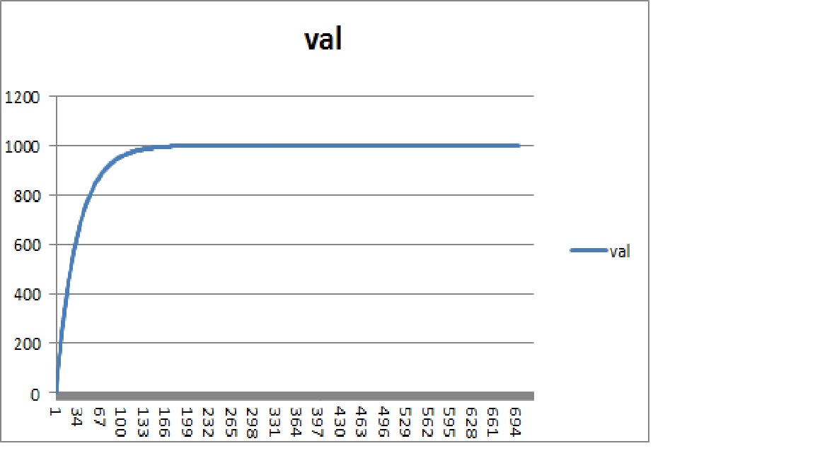
Actually it behaves more like a exponential averager. I used your code and a constant analog reading of 1000. Look at the attached diagrams (sorry for the quick and dirty excel work). One digramm ist the actual value of val which approches 1000 in an exponential manner and the other is the difference of 1000-val plotted using a logarithmic scale. As you can see the difference plot looks linear using a logarithmic y-scale therefore the function itself is exponential. I am not sure if it is possible to create a moving average filter without saving all values within the average window.
dlloyd:
The signal can change fast, i.e. using analogRead() at 8,000 reads per second, and averaging 8 reads, "val" would have a response of 1 kHz.
True but first of all I am not sure that I will always have the time to do mostly analogreads and I prefer to minimize the necessity of digital averaging if it can be achieved without to much trouble.
Yes, you're right ... thanks for plotting the results.
Another possible solution: This function takes 5 analog readings, sorts them, then returns the middle value. Very high noise rejection with no averaging.
unsigned short middle() {
  int n = 5;
  int array[] = {analogRead(A0), analogRead(A0), analogRead(A0), analogRead(A0), analogRead(A0)};

  for (int x = 0; x < n; x++) // sort readings
  {
    for (int y = 0; y < n - 1; y++)
    {
      if (array[y] > array[y + 1])
      {
        int temp = array[y + 1];
        array[y + 1] = array[y];
        array[y] = temp;
      }
    }
  }
  return array[2]; //return middle value
}
Taking the samples in such quick succession on a Due means you're sampling at way more than 1 kHz. You'll still experience the full joy of line noise. You need to average (and returning the median is essentially quite similar) over a longer period of time. Also, the sorting is rather CPU intensive.
I guess it depends on what you want to do. For signal processing, I'm merely using the Due as a means of data acquisition, and doing the filtering (Buttworth low-pass) on the PC, which has plenty of CPU power for that. Though I have some signal smoothing built into my Due code, it's optional - any signal processing I could do there is slower than just throwing the data at the PC, for the most part.
Taking the samples in such quick succession on a Due means you're sampling at way more than 1 kHz. You'll still experience the full joy of line noise.
This method works great on my Due, however I do understand it would depend on the nature of the "noise". If it's just switching noise, no problem. If it's say the 3rd harmonic of the line frequency (or similar), then it would be easy to modify the function to include a non-blocking interval between readings and to only sort after "n" readings. Also a non-blocking interval between function calls could be included.
There's nothing like an oscilloscope image to get a true picture.
I did some more testing and as it seems as improving the analog circuit reduces the problem by a factor of 2. Here is the new test setup (sligthly different then before because I want to use this circuit later on):
I am using a LMC6484N quad op-amp. When I write opamp in the next lines I always refer to one the 4 opamp in this chip.
First of all the analog reference voltage (currently I just use the 3v3 supply voltage) is buffered by using an opamp as a voltage follower.
Then I am using a voltage divider (two 5k6 resistors) to get half the reference voltage. This voltage is again buffered using an opamp as a voltage follower.
After this the signal is split in two and connected to a bnc connector (in the future I will connect a pH-probe and a Redox-probe but for the moment gave the output back by terminating the BNC connector using 50Ohm plugs).
The signal is then amplified and filtered using an opamp with a low pass filter (10MOhm + 1µF -> 16ms response time). This signal is then fed back to the Due.
Additionally I used short wires between my circuit and the DUE board.
The circuit is attached to this post as an Eagle schematic.
I used the following code for the Due:
#include <Arduino.h>

// Pins to be read
const int pin1 = A0;
const int pin2 = A1;

// Exponential Averaging factor 0 means no averaging, 1 means infinite averaging
const double avgfactor = 0.9;

// Variables for Read Values and Averaging
int value1, value2;
double value1avg = 0, value2avg = 0;


void setup()
{
 // Initialize serial port
 Serial.begin(9600);

 // Set Analog Read Resolution to 12bit to use Dues abilities
 analogReadResolution(12);
}

void loop()
{

 // Read analog voltage
 value1=analogRead(pin1);
 value2=analogRead(pin2);

 // Calculate Average Values
 value1avg=avgfactor*value1avg+(1-avgfactor)*value1;
 value2avg=avgfactor*value2avg+(1-avgfactor)*value2;

 // Output values to serial port
 Serial.print(value1);
 Serial.print(" ");
 Serial.print(value1avg);
 Serial.print(" ");
 Serial.print(value2);
 Serial.print(" ");
 Serial.println(value2avg);

 // Wait a little bit
 delay(100);
}
Getting myself a few thousand values from the serial port I get the following statistics (Min Max Average StandardDeviation):
Value1: 2034 2039 2036.33 0.78
Value1Avg: 2035.70 2036.98 2036.33 0.20
Value2: 2027 2032 2029.10 0.91
Value2Avg: 2028.43 2029.79 2029.10 0.21
As can be seen this results are actually quite good. Actually the values are that good that I am not sure that it is worth to try to improve the situation even more. I was thinking about the following possible approaches to improve the situation:
Putting a some capacitors between 5v and GND as well as 3v3 and GND to stabilize the voltages.
Using a better analog reference voltage. And use this one instead of the 3v3 supply voltage.
Using a decent 5V power supply instead of the USB power supply (this I will do anyways as there is a not to bad 5V power supply in the box the DUE will be used in and I don't see any reason to use more then one power suppply)
Create a separate analog 3V3 voltage out of the 5V in order to give the opamps a clean supply voltage. This voltage could also be used as analog reference voltage but it might be higher then the supply voltage of the SAM3X and therefore it might damage the controller.
Could anybody comment on this ideas. Which one would be most promising, which one will not work?