I'm using my own PCB with ATMega644p chip w/ Sanguino bootloader (and standard Sanguino hardware profile loaded into Arduino 1.0.1 IDE). It works great, except I cannot figure out why Analog port 1 only works as port 0
Let me explain.
ADC0_PA0 (pin 40) is connected to DS18B20 (and works just fine). I address it as A0.
I'm trying to connect ADC1_PA1 (pin 39) to photo-resistor to measure light and I address it as A1. But it doesn't work. As soon as I change it to A0 it starts to work and shows actual photo-resistor value (which changes with light amount).
I have absolutely no idea why. Pins are not connected to each other, I tested with DMM...
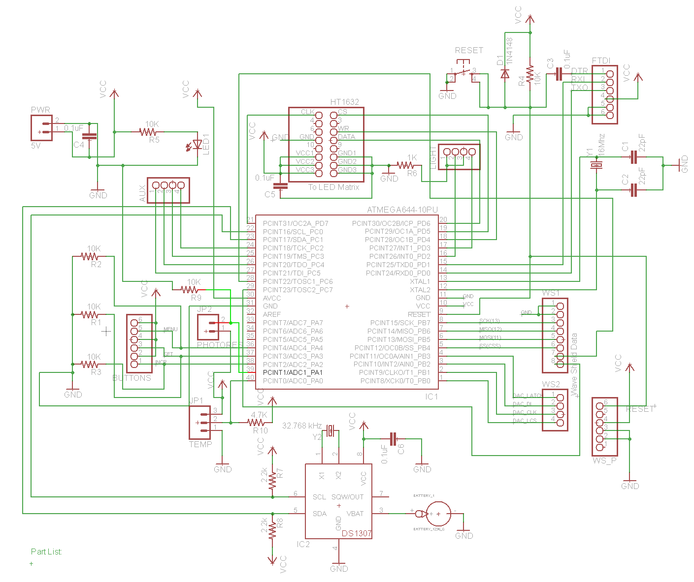
Here's simple code and schematic (JP2 is where photoresistor connected to pin 39 and pulldown resistor):
    int photocellPin = A1; // the cell and 10K pulldown are connected to a1 (and doesn't work)
    int photocellReading; // the analog reading from the sensor divider
    void setup(void) {
      Serial.begin(9600);
    }
    void loop(void) {
    photocellReading = analogRead(photocellPin);
    Serial.print("Analog reading = ");
    Serial.println(photocellReading); // the raw analog reading
    delay(1000);
    }
CrossRoads:
Could be an error in the pins_arduino.h file.
Hmmm, I can't tell I'm attaching pins_arduino.h file.
It looks like PA0 and PA1 also mapped to 31 and 30. I tried them instead of A0 and A1 and they seem to correspond. When I change it to A1 (which is supposed to be right port) I'm actually always getting reading of 1023. I tried other port such as A2-A3 and getting random readings which makes me believe something is not connected right in the schematic maybe?
I think it should maybe say (p <= 7). Also, I think the Sanguino, like all the manicbug
pinouts other than Bobuino, have the ADC channels backwards to the Bobuino/Arduino
ordering, ie, in the same order as on the chips.
Yes, maniacbug reversed the ordering for me so that A0 is near the power header, going out to A5 (and A6, A7) near the corner of the board, thus I could bring analog port pin 7 to A0 with a short trace from the uC pin to the header pin.
Thanks guys I'll give a try tonight. But I don't think it's really reversed (in my case). A0 seems to map to both PA0 and PA1...and looks like A1 is not mapped to anything analog because I always get AnalogRead (A1) = 1023, otherwise I would get almost random reading... Maybe it's mapped to digital port... Anyone knows what happens if you do AnalogRead on digital pin that's not connected?
Only sure way to know would be to use raw PORT command, but I have no idea how to AnalogRead physical port...
oric_dan:
I think it should maybe say (p <= 7). Also, I think the Sanguino, like all the manicbug
pinouts other than Bobuino, have the ADC channels backwards to the Bobuino/Arduino
ordering, ie, in the same order as on the chips.
Didn't work
Does it look from schematic that I wired it wrong?
CrossRoads:
Yes, looks like A0 normally High, and A1-2-3-4 normally Low if nothing external is connected.
Analog read on those ports should return 1023,0,0,0,0 due to the resistors you have.
Actually when polling all 6 analog ports (nothing connected) I get:
Analog reading from A0: 0
Analog reading from A1: 1023
Analog reading from A2: 769
Analog reading from A3: 476
Analog reading from A4: 332
Analog reading from A5: 0
Analog reading from A6: 0
Analog reading from A7: 0
That's because I pull A2-A4 down with 10K resistors. But A1 has same 10K resistor, yet I always get 1023 reading on that pin for some reason
I think so...
And when I connect PhotoResistor to physical A1 I get reading:
Analog reading from A0: 615 (or varies depending on how much light I get).
I will try using other analog ports instead to see if I can find one that will work and redesign my PCB based on that. Thanks!
You don't need to redesign - just read from different port names.
Eventually we'll get the mapping corrected in pins_arduino.h, or wherever it needs to be.
I have it right in bobiuno pins file, we can take that and flip it end for end or something.
CrossRoads:
You don't need to redesign - just read from different port names.
Eventually we'll get the mapping corrected in pins_arduino.h, or wherever it needs to be.
I have it right in bobiuno pins file, we can take that and flip it end for end or something.
Sorry not sure I understand
I connected photoresistor to A1 and tried reading from all 8 ports and it only responds to A0. But I already have digital temperature sensor connected A0(physical) ... So I have 2 physical ports, but both correspond to same port in pins definitions
CrossRoads:
Try replacing your pins_arduino.h with this one.
That did it (replacing pins_arduino.h)! A1 now works, but everything else is broken It's ok I'll try to mix and match pin defintions from both pins_arduino.h files.
LOL, yeah, but as messed up as it is, I'm relieved that my hardware design wasn't culprit
If I can't figure out this pin definition plan be would be to try uploading Mighty Optiboot Bootloader instead of Sanguino, and hope that my program will work with it