I am working on one project of water pressure measurement, in which i used pressure transducer which gives me output between 4-20mA Current form.
I am using one 250 ohm resistance to convert current into voltage, and than i give this voltage to ADC of arduino UNO channel 0 (A0).
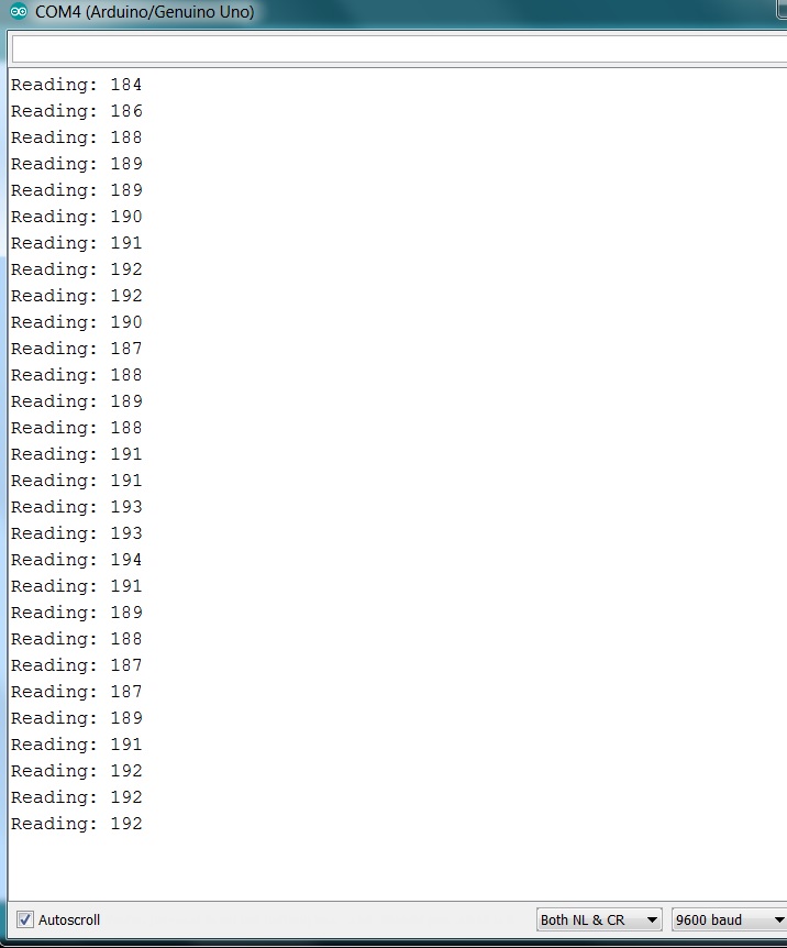
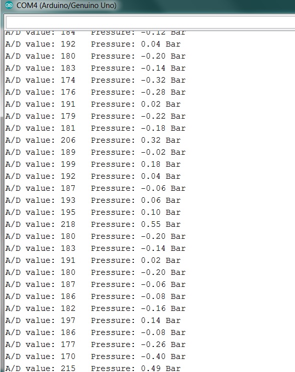
ADC reading is continuously fluctuating up to 10 decimal numbers.
I have also check by connecting multi-meter and measure sensor current reading, for particular pressure. but current reading is stable (even not fluctuate 1 or 2 points.)
also i have checked voltage value after 250 Ohms +Ve and ground. converted voltage is also showing very stable.
but why ADC reading is fluctuating..?
i am using arduino uno, i doesn't have any changes in AREF, AVCC etc...
I just simple taking ADC Reading and send it serially to serial monitor.
my code is as below...
const int analogInPin = A0;  // Analog input pin that the potentiometer is attached to

int sensorValue = 0;        // value read from the pot

void setup()
{
  // initialize serial communications at 9600 bps:
  Serial.begin(9600);
}


void loop()
{
  // read the analog in value:
  sensorValue = analogRead(analogInPin);


  // print the results to the Serial Monitor:
  Serial.print("Reading: ");
  Serial.println(sensorValue);

  delay(1000);
}
By default the ADC uses the 5v supply as it’s reference , of this has noise on it that would affect the reading. You can switch to an internal reference if that is the problem.
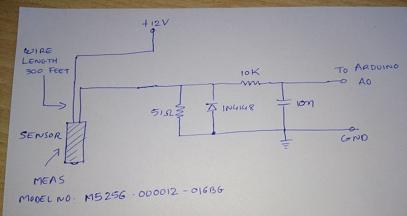
Use a 51ohm resistor (standard 1% E24 value) instead of a 250ohm resistor.
And Arduino's internal 1.1volt Aref instead ot the potentially unstable default Aref.
You might also want to add protection and filtering (see diagram).
Leo..
Sensor A/D reading should not fluctuate more than one A/D value.
Is that 12volt sensor supply near the Arduino or near the sensor.
How did you connect sensor ground and/or 12volt supply ground to the Arduino.
How do you power the Arduino.
(I asked for a real picture of the setup, to check all of the above)
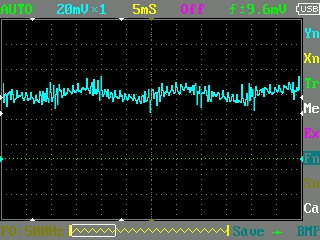
Is this used in a noisy (electrical) environment.
Did you use twisted or shielded cable (300ft can be a powerful aerial).
Do you see an improvement if you add a 100uF electrolytic cap across the 51ohm resistor.
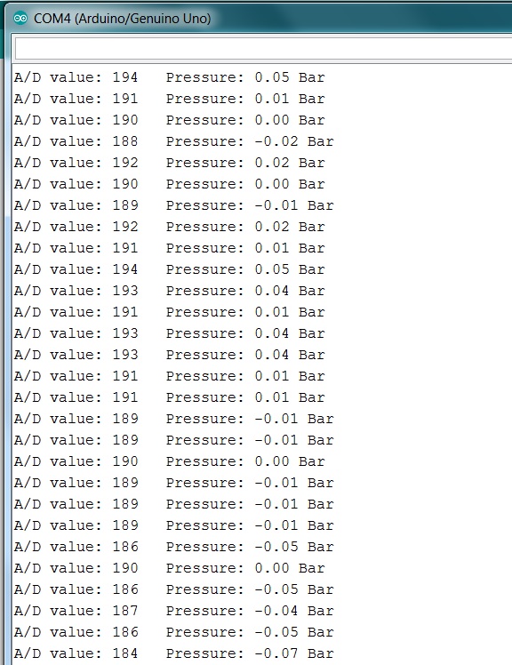
pressure = (sensorValue - offset) * 10.0 / (fullScale - offset);
should ofcourse be
pressure = (sensorValue - offset) * 16.0 / (fullScale - offset);
if you use a 0-16 bar sensor. Assuming you want the readout in bar.
Leo..
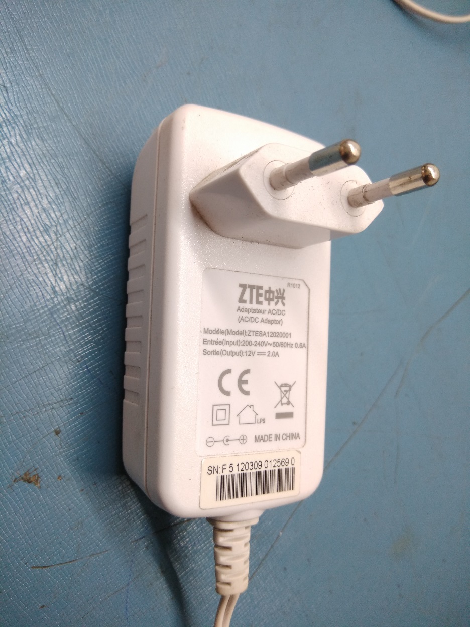
I am using 12V DC SMPS adeptor for power supply to Sensor.
i connected arduino with my PC using USB Cable for power and serial communication.
No there is no any electrical noisy environment.
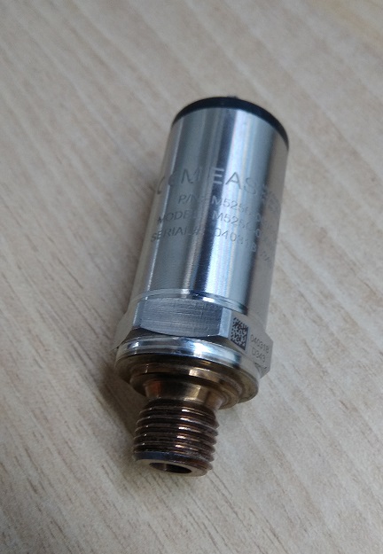
Actually i want to measure water depth inside ground bore-well and data logger, directly this pressure sensor is not able to for that i have covered my sensor with special corrosion free copper material to avoid damage due to high pressure. (sensor photo is attached).
i am not using full range of sensor, for 100 feet measurement span is only between 4mA to 6mA.
BHARGAV_1990:
yes i have connected 100n Capacitor across 51 Ohm resistor.
Read that post again. I didn't say 100n.
Try 100uF electrolytic (or bigger).
Remove if it doesn't help.
You should have tested the sensor first without the long wire.
Maybe the metal casing of the sensor needs to be grounded (to Arduino ground).
Did you use twisted/shielded wire.
Leo..
P.S. Tested the circuit with an Uno and a constant current, and it sometimes only jumps one A/D value.
It must be the sensor an/or wiring causing it.
If your well has a steel casing and there are ground currents flowing through the casing, it could induce noise into your sensor. If the well does have a steel casing, attach the sensor ground to the casing.
Try 100uF electrolytic (or bigger).
Remove if it doesn't help.
i have tried 100uF Capacitor, but there is no any change.
You should have tested the sensor first without the long wire.
Sensor is fixed with wire, metal casing is permanently attached with wire and sensor by applying hardner and rasin.
now it is not possible to make separate wire and sensor.
Maybe the metal casing of the sensor needs to be grounded (to Arduino ground)
When i trying to connect metal casing with arduino ground, arduino usb port becomes disconnect, i have try several times but every time arduino USB port disconnect.
Did you use twisted/shielded wire.
wire for sensor i have used is simple electrical cable 1 sqmm. 2 core.
Paul_KD7HB:
If your well has a steel casing and there are ground currents flowing through the casing, it could induce noise into your sensor. If the well does have a steel casing, attach the sensor ground to the casing.
Paul
No, well has no any steel casing, first i am testing sensor at outside the well, for 4mA Current. without any pressure.
BHARGAV_1990:
When i trying to connect metal casing with arduino ground, arduino usb port becomes disconnect, i have try several times but every time arduino USB port disconnect.
Can't explain that.
What sort of 12volt supply are you using .
Is it a small 12volt plug-in supply (no ground), or a grounded metal-frame supply.
Post a picture.