I am currently attempting to interface the AK09970N with the Arduino Mega2560. Unfortunately, my code never moves past the endTransmission() statement. What did I do wrong???
 void setup() {
  // initialize arduino baud rate at sensor's baud rate
  Serial.begin(100);

  // set SCL pin rate to 100 Hz
  Wire.setClock(100);

  // Initiate Wire library
  Wire.begin();

  // set up ODINT pin
  pinMode(ODINT_PIN, INPUT_PULLUP);
  digitalWrite(ODINT_PIN, HIGH);

  // I2C power on
  pinMode(RST_PIN, OUTPUT);
  digitalWrite(RST_PIN, LOW);

  Serial.println("Checkpoint 1");


  // set sensor to 100 Hz high sensitivity measurement mode
  Wire.beginTransmission(AKAddress);
  Wire.write(WRITE);
  Wire.write(CNTL2);
  Wire.write(MODE_3);
  Wire.endTransmission(true));
}
A motor car is moving at 500 m/hr. Is this car in motion?
Your ATmega328P MCU of the UNO/NANO/MEGA is running at 16 MHz; you want to exchange data between two devices at 100 bit/sec using I2C Bus. Do you think that the I2C bus will become active? Please, read this as said in Post#3.
You can remove the Wire.setClock(), then at least you do not use it in the wrong way
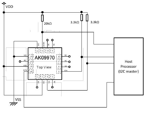
According to the datasheet, the AK09970N is a 3.3V sensor.
The Arduino Mega 2560 is a 5V Arduino board, and it has 10k pullup resistors from SDA to 5V and from SCL to 5V.
Some 3.3V sensors are broken when you connect the SDA and SCL of the Arduino Mega 2560 to those sensors.
If that is not enough, you push 5V into the ODINT pin of the sensor.
When a sketch stops inside the Wire.endTransmission(), there might be a shortcut of SDA to GND or from SCL to GND or a shortcut between SDA and SCL. In this case, you might also have blown the sensor.
Assume that the sensor is broken and start again without destroying the sensor with 5V. You better use a 3.3V Arduino board.
My endTransmission() still never ends. If I place a print statement right after the line, it never prints. In reference to the 5V thing, I did make sure to choose the 3.3V setting on the board. Furthermore, to ensure that the sensor wasn't shorted, I checked that the ODINT, SCL, and SDA pin had appropriate voltage drops, which they did.
What should the baud rate be? I know that standard mode is 100 kHz and that the measurement speed is 100 Hz. I chose 100 Hz, because that's how quickly the sensor measured the data.
Please, remove the Wire.setClock() Just remove it.
For everyone else: the source code for Wire.setClock() is kind of dumb. I did not calculate the result, but the resulting speed could be between 40kHz and 800kHz.
How did you create the voltage drop for SDA, SCL, and ODINT ?
I think that you might have connected a 5V 40 mA digital output form the Arduino Mega 2560 board directly connected to the ODINT pin of the sensor. Does the sensor get hot ? Do you see the magic smoke ?
Koepel:
When a sketch stops inside the Wire.endTransmission(), there might be a shortcut of SDA to GND or from SCL to GND or a shortcut between SDA and SCL. In this case, you might also have blown the sensor.
The Master could not come out-of Wire.begin/Wire.end session due to (very probably) non-availability of the ACK signal/pulse from the Slave. The following diagram indicates that the SDA line quickly assumes LH level after the sampling of the ACK (present or not present) signal, and the SCK is already at LH level during the sampling of the ACK signal. If ACK is not received, SCL will be stretching as much as is needed until WDT/waiting boundary comes into action. Therefore, it is hard to justify the opinion that the SDA/SCL lines might get shorted together or with GND during this situation?
Koepel:
I think that you might have connected a 5V 40 mA digital output form the Arduino Mega 2560 board
The Arduino Wire library can get stuck in a while-loop. I have not heard that a timing problem could cause it. You can try the I2C scanner and connect SDA or SCL to GND and see what happens
The 40 mA is the shortcut current to GND. From 5V to 3.3V will not be as much as 40 mA, but I assume that it is above 20 mA.
The 20 mA is the maximum current for normal operation. Most of us don't like to go beyond the 20 mA. With a capacitive load (for example a piezo element) the peak currents can be 40 mA.
I mentioned the 5V 40 mA to add some drama to it :o Some sensors go into an automatic sleep mode and use almost no current, in that case pushing 5V 1 mA or perhaps 0.1 mA into the sensor might already damage the sensor.