Hey all,
I am trying to drive an old DDU-1 Game Plan Board using an arduino.
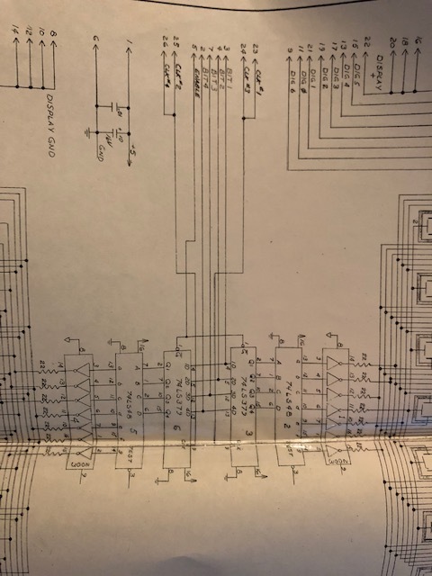
This board has two 74LS379 chips that each load a 74LS48 chip to drive a 7-segment display. There are 7 Digits connected to each 379 circuit (See: Attachment IMG_1620.jpg). Currently I have the following code:
const int DIGIT_PINS[] = {A6, A0, A1, A2, A3, A4, A5};
const int CLOCK_PINS[] = {5, 11};
const int BCD_PINS[] = {6, 7, 8, 9};

void setup() {
  Serial.begin(115200);
  // put your setup code here, to run once:
  for (int pin = 0; pin < 7; pin++) {
    pinMode(DIGIT_PINS[pin], OUTPUT);
    digitalWrite(DIGIT_PINS[pin], LOW);
  }

  for (int pin = 1; pin < 14; pin++) {
    pinMode(pin, OUTPUT);
    digitalWrite(pin, LOW);
  }
  digitalWrite(CLOCK_PINS[0], LOW);
  digitalWrite(CLOCK_PINS[1], LOW);
  digitalWrite(4, LOW);
}


void loop() {
  for (int pin = 0; pin < 7; pin++) {
    for(int clock_pin=0; clock_pin < 2; clock_pin++) {
        BCDSet(pin);
        delayMicroseconds(250);
        digitalWrite(CLOCK_PINS[clock_pin], LOW);
        digitalWrite(DIGIT_PINS[pin], HIGH);
        delayMicroseconds(250);
        digitalWrite(DIGIT_PINS[pin], LOW);
        digitalWrite(CLOCK_PINS[clock_pin], HIGH);

    }
  }
}

void BCDSet(byte number)
{
  for (int i=0;i<4;i++)
  {
    if (bitRead(number, i)==1)
    {
      digitalWrite(BCD_PINS[i], HIGH);
    }
    else
    {
      digitalWrite(BCD_PINS[i], LOW);
    }
  }
}
Which is stepping through each of the 7 digits, for each step it loads a number via the 1D-4D lines on the 74LS379 and clocks the CK port (one for each of the 74LS379 chips).
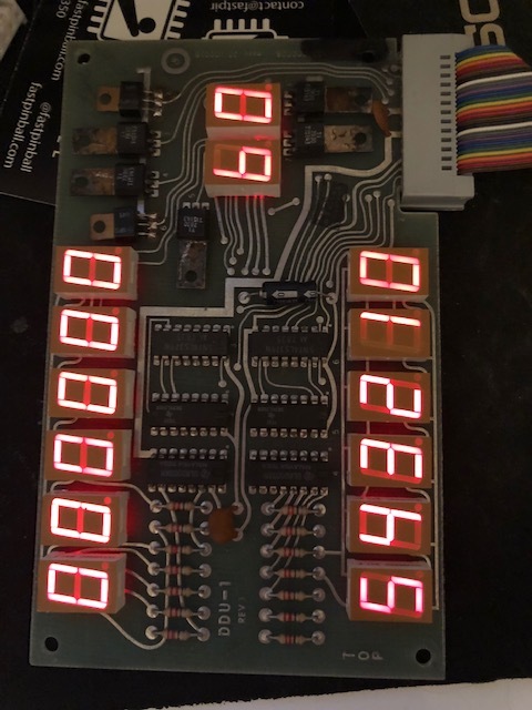
I expected this code to result in both the top display and bottom display to have 0123456 as their value. (Note the last digit is located to the side (See: Attachment IMG_1619.jpg). As you can see the top circuit is resulting in 0000000 and the bottom 0123456.
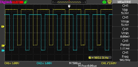
I have checked the clock pins coming into both the 74LS379 chips (See: Attachment QC000003.JPG).
I guess I am missing something obvious about how these chips work/how I can drive them from the Arduino. Hoping someone might have a pointer to get me moving forward again.
Thanks