In this Arduino Tutorial I will show you how you can make this cool looking radar using the Arduino Board and the Processing Development Environment. You can watch the following video or read the written tutorial below for more details.
Video:Arduino Radar Project - YouTube
Overview
All you need for this Arduino Project is an Ultrasonic Sensor for detecting the objects, a small hobbyist Servo Motor for rotating the sensor and an Arduino Board for controlling them. You can watch the following video or read the written tutorial below.
Components needed for this Arduino Project
You can get these components from any of the sites below:
Ultrasonic sensor HC- SR04……. Amazon / Banggood / GearBest / DealExtreme / ICStation
Servo Motor…………………………… Amazon / Banggood / GearBest / DealExtreme / ICStation
Arduino Board……………………….. Amazon / Banggood / GearBest / DealExtreme / ICStation
Breadboard and Jump Wires….. Amazon / Banggood / GearBest / DealExtreme / ICStation
*Please note: You may need Fusion PCB Service to make it works better!
Building the device
First I made a cardboard stand for connecting the Ultrasonic sensor to the Servo motor. I folded it like it’s shown on the picture below, glued it and secured to the servo motor using a screw like this.

Also I attached a pin header on which I soldered 4 jumper wires for connecting the sensor.

Finally I secured the servo motor to the Arduino Board using an elastic band.

There are also some special mount bracket for the ultrasonic sensor from Banggod. You can get them from the following links:
Cartoon Ultrasonic Sensor Mounting Bracket For HC-SR04
Acrylic Ultrasonic Sensor Mounting Bracket For HC-SR04 Module
HC-SR04 Ultrasonic Module Distance Measuring Mount Bracket
Circuit Schematics
I connected the Ultrasonic Sensor HC-SR04 to the pins number 10 and 11 and the servo motor to the pin number 12 on the Arduino Board.

Source codes
Now we need to make a code and upload it to the Arduino Board that will enable the interaction between the Arduino and the Processing IDE. For understanding how the connection works click here to visit my Arduino and Processing Tutorial.

Here’s the Arduino Source Code with description of each line of the code:
// Includes the Servo library
#include <Servo.h>.
// Defines Tirg and Echo pins of the Ultrasonic Sensor
const int trigPin = 10;
const int echoPin = 11;
// Variables for the duration and the distance
long duration;
int distance;
Servo myServo; // Creates a servo object for controlling the servo motor
void setup() {
pinMode(trigPin, OUTPUT); // Sets the trigPin as an Output
pinMode(echoPin, INPUT); // Sets the echoPin as an Input
Serial.begin(9600);
myServo.attach(12); // Defines on which pin is the servo motor attached
}
void loop() {
// rotates the servo motor from 15 to 165 degrees
for(int i=15;i<=165;i++){
myServo.write(i);
delay(30);
distance = calculateDistance();// Calls a function for calculating the distance measured by the Ultrasonic sensor for each degree
Serial.print(i); // Sends the current degree into the Serial Port
Serial.print(","); // Sends addition character right next to the previous value needed later in the Processing IDE for indexing
Serial.print(distance); // Sends the distance value into the Serial Port
Serial.print("."); // Sends addition character right next to the previous value needed later in the Processing IDE for indexing
}
// Repeats the previous lines from 165 to 15 degrees
for(int i=165;i>15;i--){
myServo.write(i);
delay(30);
distance = calculateDistance();
Serial.print(i);
Serial.print(",");
Serial.print(distance);
Serial.print(".");
}
}
// Function for calculating the distance measured by the Ultrasonic sensor
int calculateDistance(){
digitalWrite(trigPin, LOW);
delayMicroseconds(2);
// Sets the trigPin on HIGH state for 10 micro seconds
digitalWrite(trigPin, HIGH);
delayMicroseconds(10);
digitalWrite(trigPin, LOW);
duration = pulseIn(echoPin, HIGH); // Reads the echoPin, returns the sound wave travel time in microseconds
distance= duration*0.034/2;
return distance;
}
Now we will receive the values for the angle and the distance measured by the sensor from the Arduino Board into the Processing IDE using the SerialEvent() function which reads the data from the Serial Port and we will put the values of the angle and the distance into the variables iAngle and iDistance. These variable will be used for drawing the radar, the lines, the detected objects and some of the text.

For drawing the radar I made this function drawRadar() which consist of arc() and line() functions.
void drawRadar() {
pushMatrix();
translate(960,1000); // moves the starting coordinats to new location
noFill();
strokeWeight(2);
stroke(98,245,31);
// draws the arc lines
arc(0,0,1800,1800,PI,TWO_PI);
arc(0,0,1400,1400,PI,TWO_PI);
arc(0,0,1000,1000,PI,TWO_PI);
arc(0,0,600,600,PI,TWO_PI);
// draws the angle lines
line(-960,0,960,0);
line(0,0,-960cos(radians(30)),-960sin(radians(30)));
line(0,0,-960cos(radians(60)),-960sin(radians(60)));
line(0,0,-960cos(radians(90)),-960sin(radians(90)));
line(0,0,-960cos(radians(120)),-960sin(radians(120)));
line(0,0,-960cos(radians(150)),-960sin(radians(150)));
line(-960*cos(radians(30)),0,960,0);
popMatrix();
}
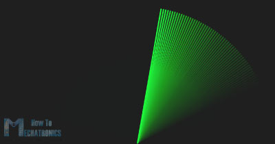
For drawing the line that is moving along the radar I made this function drawLine(). Its center of rotation is set with the translate() function and using the line() function in which the iAngle variable is used the line is redrawn for each degree.
void drawLine() {
pushMatrix();
strokeWeight(9);
stroke(30,250,60);
translate(960,1000); // moves the starting coordinats to new location
line(0,0,950cos(radians(iAngle)),-950sin(radians(iAngle))); // draws the line according to the angle
popMatrix();
}
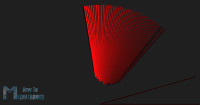
For drawing the detected objects I made this drawObject() function. It gets the distance from ultrasonic sensor, transforms it into pixels and in combination with the angle of the sensor draws the object on the radar.
void drawObject() {
pushMatrix();
translate(960,1000); // moves the starting coordinats to new location
strokeWeight(9);
stroke(255,10,10); // red color
pixsDistance = iDistance22.5; // covers the distance from the sensor from cm to pixels
// limiting the range to 40 cms
if(iDistance<40){
// draws the object according to the angle and the distance
line(pixsDistancecos(radians(iAngle)),-pixsDistancesin(radians(iAngle)),950cos(radians(iAngle)),-950*sin(radians(iAngle)));
}
popMatrix();
}
For the text on the screen I made the drawText() function which draws texts on particular locations.
All of these functions are called in the main draw() function which repeats all the time and draws the screen. Also here I am using this fill() function with 2 parameters for simulating motion blur and slow fade of the moving line.
void draw() {
fill(98,245,31);
textFont(orcFont);
// simulating motion blur and slow fade of the moving line
noStroke();
fill(0,4);
rect(0, 0, width, 1010);
fill(98,245,31); // green color
// calls the functions for drawing the radar
drawRadar();
drawLine();
drawObject();
drawText();
}
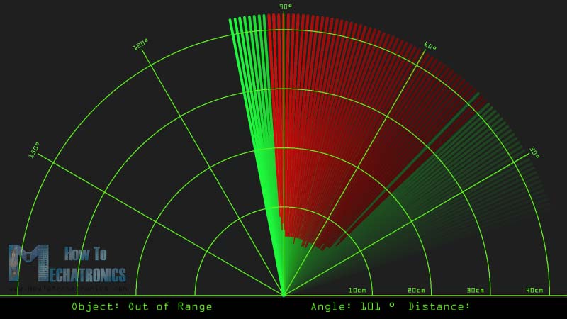
Here’s the final appearance of the radar:
To see the whole source code, please visit :http://seeed.cc/project_detail.html?id=1846