I'm wanting to control 3 different electromagnets. I have a relay and a 12V, 3A power supply, which should be enough to power all 3 magnets (they all draw ~0.5 A or less). However, I'm noticing a current spike when a magnet is discharged. Is there any potential for damage when the current to a magnet is cut? Either to my relay or the other magnets? I'm assuming there is no risk to the Arduino, since I'm powering the relay from its own power supply as well.
Oh, and while I'm here... I read somewhere (I think from an Amazon product Q/A. Very reliable source, I know) to be careful not to supply too much current to the magnets. That didn't seem to make sense to me. A magnet will only draw what it draws, regardless of heat, correct?
Completely - normally opening the circuit to an electromagnet without protective circuitry leads to
heavy arcing of relay contacts, even welding them shut. Semiconductor switching devices can
be destroyed immediately.
For DC circuits a simple free-wheel diode across the winding is normally used, simple and effective
(but can slow down the magnetic field dissipation).
And its not a current spike, its a voltage spike.
Sorry, across the winding? Would a diode in series with the magnet do the trick?
Also, I said current spike because, when reading the current, it jumped from 0.5 A up to 2 A or more.
Sorry, across the winding? Would a diode in series with the magnet do the trick?
Yes across the windings a series diode would not work.
Bapstack:
Sorry, across the winding? Would a diode in series with the magnet do the trick?Also, I said current spike because, when reading the current, it jumped from 0.5 A up to 2 A or more.
In series will mean a dead diode as well as arcing contacts, across the winding and nice well behaved
circuit.
[ of course it must be the right way round, cathode to +ve end of winding ]
Ok, sounds good. Thank you guys for your help. Should I have a resistor in series with the magnet, or will the internal resistance be enough?
Additionally, does it make a difference if the relay comes before or after the magnet in the circuit?
The diode goes "backwards" across so no current flows through the diode when power is applied. When the magnetic field collapses the current keeps flowing in the same direction through the coil, but since the coil is now acting as a generator the voltage is reversed, and the reverse voltage gets "shorted out" by the diode. (If you understand how current flows in a simple battery & resistor circuit, the current flows from positive-to-negative through the resistor, but from negative-to-positive inside the battery.)
Also, I said current spike because, when reading the current, it jumped from 0.5 A up to 2 A or more.
There might be something wrong with your measurement. (Multimeters only read AC & DC voltage/current when it's constant or changing slowly.)
That didn't seem to make sense to me. A magnet will only draw what it draws, regardless of heat, correct?
[u]Ohm's Law[/u]. (Current depends on the applied voltage and the resistance of the coil.)
Should I have a resistor in series with the magnet, or will the internal resistance be enough?
Usually not.., it would depend on the voltage rating for the coil. Usually you don't want a resistor because it will dissipate heat and waste power.
Additionally, does it make a difference if the relay comes before or after the magnet in the circuit?
No. No matter where you "break" the circuit, current-flow (from the power supply) will stop. And the relay is simply an electrically-controlled, electrically-isolated set of switch contacts.
BTW - The relay coil should also have a diode across it.
DVDdoug:
[u]Ohm's Law[/u]. (Current depends on the applied voltage and the resistance of the coil.)
Right. Intro to circuits at least taught me that much. ![]() I guess I was asking if the resistance of the coil varies with heat (appears that the answer is no).
I guess I was asking if the resistance of the coil varies with heat (appears that the answer is no).
DVDdoug:
The relay coil should also have a diode across it.
[u]So this[/u], with the diode across across the relay? Obviously positioned so as not to short the relay. What exactly does this do? I get that the first diode allows the magnet to discharge, sending the inductor's current back around through the magnet and not to the relay. What is the purpose of diode #2?
The second diode does exactly the same thing only for the relay coil.
Drop the resistor and just supply the coil with the right voltage otherwise the resistor is probably going to burn up.
Grumpy_Mike:
The second LED does exactly the same thing only for the relay coil.
Drop the resistor and just supply the coil with the right voltage otherwise the resistor is probably going to burn up.
[/quoteWhat Mike said, but with a plain old diode. You'd zap a led coming and going with 12v
Hi,
This may help;
https://www.westfloridacomponents.com/blog/what-is-back-emf-and-what-does-it-do/
Tom.... ![]()
Would such a diode be necessary with this linear actuator? I don't read the same voltage spike when I disconnect the actuator, so does that indicate that a flyback diode would be unnecessary, or that it's already built in?
I'm assuming there is no risk to the Arduino, since I'm powering the relay from its own power supply as well.
I don't think that you should regard that as completely true.
I think that you should add the diode protection, before you regret it.
Would such a diode be necessary with this linear actuator?
You need a diode across any coil you are switching.
Hi,
The manufacturer site for your actuator, also a manual is available, it may tell you how its motor is configured.
Tom.... ![]()
Bapstack:
I'm wanting to control 3 different electromagnets. I have a relay and a 12V, 3A power supply, which should be enough to power all 3 magnets (they all draw ~0.5 A or less). However, I'm noticing a current spike when a magnet is discharged. Is there any potential for damage when the current to a magnet is cut? Either to my relay or the other magnets? I'm assuming there is no risk to the Arduino, since I'm powering the relay from its own power supply as well.
The electromagnet stores energy as a magnetic field when energized. When de-energized, the magnetic field collapses and generates a voltage proportional to how fast it collapses (Faraday's law).
Since the field collapses VERY fast, it induces a vert short but very high voltage into the windings (that's how an automobile ignition coil works, by the way).
The solution is to place a diode (something like a 1N4001) across the coil, in the direction that it does NOT conduct when the coil is energized. Since the high voltage "kickback" occurs in the opposite polarity, the diode will conduct and absorb the spike.
There is very high VOLTAGE in the spike, but very little CURRENT, so a small diode like the 1N4001 can snub (absorb) the spike with ease.
Hope this helps.
Bapstack:
Would such a diode be necessary with this linear actuator? I don't read the same voltage spike when I disconnect the actuator, so does that indicate that a flyback diode would be unnecessary, or that it's already built in?
That linear actuator is a motor driven lead screw. The motor, being basically an electromagnetic device, will produce a high voltage kick back like an electromagnet will.
But, since the motor windings are much smaller (that is, less wire, less turns and less inductance) than a big electromagnet, the amount of kick-back you get is most probably a lot smaller.
However, placing a diode across the motor won't work because the actuator needs one polarity to extend and one polarity to retract. A diode would be a short circuit in one direction!
The solution here is to use an RC snubber. Take about a 10 ohm resistor in series with a NON-POLARIZED capacitor of about 1 to 10 uF and place that across the motor.
It will slow down the rate that the magnetic field collapses, and since the kick-back voltage is proportional to the speed that the field collapses, the kick-back will last longer, but have a lower voltage.
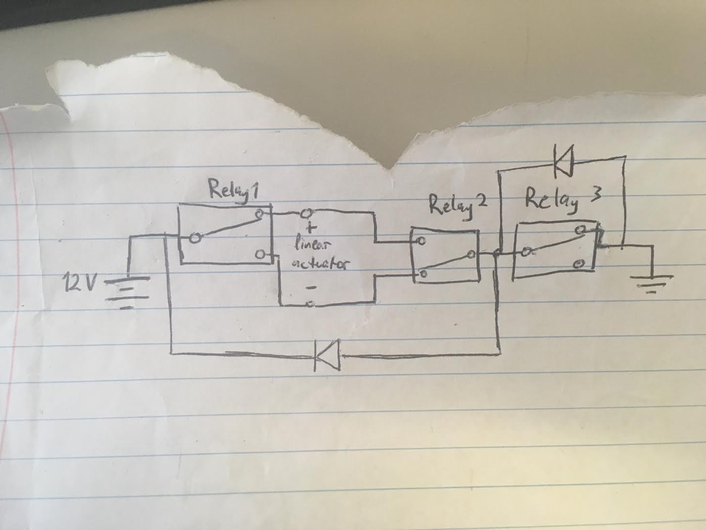
Actually, I was just considering that. Would the following solution work?
Relay 3 is just to make sure that both relay 1 and 2 are both in position before current flows. I'm still not entirely confident about the purpose of the diode on the right, or if it would even do anything useful as I have it drawn.
And I did take a look at the manual. Didn't seem to indicate a flyback diode built in, and the Amazon seller got back to me and recommended a diode across the actuator. So there we have it.
edit: Image doesn't appear to be showing up. Imgur: The magic of the Internet
![[u]So this[/u]](https://upload.wikimedia.org/wikipedia/commons/thumb/9/92/Flyback_Diode.svg/300px-Flyback_Diode.svg.png)