I've read this tutorial as well as several posts in this forum about H-Bridges, but for the life of me I can't understand why the "top" 2 transistors in the classic circuit need to be PNP while the bottom two should be NPN. The way I see it (for what it's worth), if I apply a voltage to the base, current should flow between the emitter and collector. If I do that to diagonally-opposed NPN transistors, what would be the problem? In other words, why can't I use 4 NPN transistors?
Terry the real problem is the "Top npn is an 'Emitter follower' and the bottom one a true switch thus there will never be more than Vcc- .6 - .7V applied to the load. Where when using a complimentary pair (Ptop and Nbot) both are switches, the N switches ground and the P switches + supply. You 'pull' current from the P base to turn it on and 'push' current to the N to switch the bridge to conduct. It is hard sometimes to visualize the reversal of polarity in the PNP. I do it by remembering that N is always base positive to the emitter to conduct and the P is always base neg to the emitter to conduct so one pulls down the P and pulls up the N to turn on the bridge... hope it helps...
Still not getting it, I'm afraid. Based on the tutorial link in my original post, I drew up something similar (ignoring the diodes) using only NPNs. Could someone please explains in simple terms the reasons why this fails/sizzles/explodes or otherwise (assuming I only apply positive voltage to diagonally opposed pairs at a time)?
As doc said above... only the BOTTOM pair of transistors are able to act like "switches" in your drawing... and you really want all 4 to behave that way (that's why you want PNP on the positive voltage side). If the transistors on top won't act like a switch... well, put another way... if you got it to work for you... you would then come back to us and ask... "why is my motor only going s l o w ?"
One concept for the N issues being on top might be in the realm of the N on top emitter flow has to flow thru the load itself which might result in lower conduction issues across the transistor. A lower base voltage than collector voltage may also play into lower performance. There are MOSFET H-bridges that use N MOSFETS on the high side. These H-bridges have boot strap charge pump type circuits that ensure the MOSFET gate voltage is higher than the voltage being switched.
These H-bridges have boot strap charge pump type circuits that ensure the MOSFET gate voltage is higher than the voltage being switched.
Exactly. Same deal for NPN high side switches.
As somebody, hopefully me, said:
it makes the design and implementation of the driving circuitry more difficult and expensive.
Transistors don't know where their next meal is coming from, or who feeds them base current.
For a high-side NPN to be fully turned on, just like a low-side NPN, there needs to be a voltage source higher than the collector supply. An NPN in saturation (The Emitter-Collector voltage is .2 to .4 volts, say) has a base voltage higher than the collector voltage. It's gotta come from somewhere.
Some power supply circuits, like my venerable HP bench supplies, have a separate higher-voltage supply just to be able to turn the NPN output transistors full on.
Ischia, you asked a perfectly good question, and the fact that you are not immediately satisfied with the answers tells me that you have the disposition to become a really good designer. Of whatever you care enough about designing. You are probably not happy with Skool As It Is, and that's good. I say this as a person who has taught at SUNY and IBM, and personally heard Buckminister Fuller say, "Dare To Be Naive".. Keep on pushing until you understand it!
Although it is trickier to drive an all NPN H-bridge properly, its relatively easy for all-n-channel MOSFET H-bridges because of the rich variety of cheap driver IC's available specifically for the purpose.
n-channel FETs and NPN bipolar transistors are inherently better-performing than p-channel and PNP devices so it makes sense to use them throughout an H-bridge for improved switching speed and power-efficiency.
For a little 5V H-bridge on a breadboard built from bipolar transistors though the NPN + PNP H-bridge design is the simplest DIY one (I've done just that a few times to drive small motors). Bipolar transistors also have the ability to do crude current limiting (you provide just enough base current to saturate under normal conditions - fault currents are then limited by the current gain. MOSFETs tend to pull a LARGE current if there's an accidental short and some sort of protection circuit or fuse is generally a good idea.
@terryking228: Thank you for your kind words. I guess I'll come back to thinking about the issue after I've made some progress in electronics, as I have difficulties understanding even half of the replies above...
Actually, here's another way to ask the same question. Please bear with me and remember everyone was a newbie once.
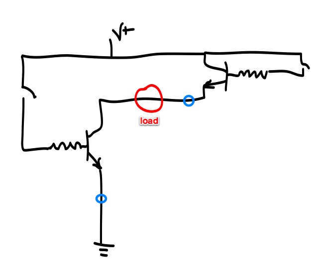
Still following the first example circuit on this page, I assembled a circuit on a breadboard which represents only one diagonal pair, bottom-left to upper-right, using only NPN transistors. It looks like the attached diagram, the blue circles are just LED+resistor pairs which I've put to see if the switches work.
Obviously, the bottom-left part works (the switch connected to the base turns on the LED attached to the emitter) while the upper-right part doesn't, even while keeping the bottom-left switch in the closed position (and therefore creating a path to ground through the load).
Why is that, and how will a PNP transistor in the upper-right section make this work?
This is how I think of it ... I may be wrong but it makes sense.
Transistors have 3 legs, where the collector/emitter pair are the "output" and the base is the "input". But we all know that you never control a circuit with one wire ... remember to connect the ground!
So you have to ask, to turn the transistor on, it must be current flowing between base/.
So what is this something? For a BJT transistor it is the emitter. And since you connect the emitter to ground for the bottom two transistors, then it is the base/ground difference that turns on the transistor.
If we look at the image on the page you mentioned:
The bottom two transistors are doing that. The emitters are connected to ground, and it is the base/ground potential that turns them on. But the top two do not have their emitters connected to ground, so we do not have a voltage reference "to ground" there.
In fact the emitters are connected to 5V (or whatever). So we have to flip the whole thing over by using PNP transistors. Now it is the base/5V difference that turns the transistor on. It is still the difference between the base and the emitter, but with reverse polarity we can now turn the transistor off by putting 5V at the base (assuming the supply rail is 5V) and turn it on by putting 0V at the base. In effect, you could say that the transistor is turned on by putting -5V at the base, since the polarity of the silicon is the other way around.
If you use all NPN transistors, as in one of your sketches, the motor is "in the way" of the circuit between the base and the emitter, and thus your attempt to turn on the top transistors will be thwarted (partly or completely) by the resistance of the motor coil.
@Nick Gammon: Thanks to your explanation I'm beginning to see the light here. One last thing, though: suppose there was no motor or any other load "in the way" as you say. Even then, the top right NPN transistor still doesn't work although the bottom-left transistor is kept "active" (i.e. +5V to base, current flowing from C to E) and therefore opening a clear path to ground for the top-right one.
EDIT: actually the top-right NPN works with no load, I was silly enough to assume that a single LED as a load (in the place of the motor) would be insignificant, but it wasn't. If you remove the load and keep the bottom-left switch closed (i.e. transistor active), then the top-right NPN works just fine.
I appreciate your taking the time to explain all of this as it finally makes sense to me.
Nick, your arrows are pointing towards you pnp transistors, I think they should be pointing away from them as you sink the base on the pnp's not drive them but you've explained it well,
Here is a circuit i like, it uses a small npn to sink the pnp base and drive the npn base at the same time requiring only switching between forward and reverse, I have tried and tested this circuit and it works well
And the subject has been well covered too both from a lay standpoint and a techie standpoint. PNP transistors are difficult for most to understand. I do it by remembering they are opposite... JAM current into an NPN base to turn it on (Neg earth or ground reference) and Pull current OUT of the PNP base to turn it on both turning on exactly the same way just one reversed from the other and most important is that the most positive element (again neg earth) for a PNP Must be the Emitter and for an NPN the collector of course. I had a hell of a time with that as when transistors became commercially available in the late 50's 59-60 they were all pnp types (my first one was a bright blue CK722 from Raytheon... terrible little delicate and very leaky devices that cost $10.00 ea (a Very respectable sum converted to today's dollars).
I learned on vacuum tubes and what a journey it's been... I remember the first Blue LED's from Cree, really delicate > 5 mA was usually fatal.
and about $30.00 ea If I remember right...
From tubes to Quantum physics all in 50 years. WOW
This discussion is a great example of the way people on this forum are into IdeaStuff and helping others.
From tubes to Quantum physics all in 50 years. WOW
I am very fortunate to have been able to take this Trip, in 60 years in my case since I first built something with a vacuum tube.
WARNING: Terry feels Another Story coming on...
Just when I thought all that was obsolete knowledge, two guys showed up at my office door at IBM. "Uh, we heard you know something about vacuum tubes.".
"Yeah, did that in the Old Days!".
"We have this electron beam welder. It just stopped working. It has a huge tube in it, a 4-1000A. Every heard of something like that?"
"Well, it's almost exactly like a 4-400A, but bigger. It must look like this:". (Reaching up on my shelf and taking down the 4-400A souvenir from my Broadcast days in it's box, and taking it out).
"Yes! That's exactly what it looks like! You have one on your shelf?? Wow!"
"OK, what's the symptom? Let's go look at your machine"...
"The high voltage is there, the tube filament lights up, but almost no beam current any more."
...An hour later, we determined that the Screen resistor was open (my first guess). I brought a workable large temporary resistor in from my Ham Radio junkbox at home the next day and it worked until the right replacement part came in from Siemens...
For the last 30 minutes I've been staring at the circuit posted by P18F4550.
From a practical standpoint, it makes it easier to see how, when for instance X2-2 on the right gets 5V (say), T6 opens and triggers T2 and T4.
However, I'm trying to understand why this works: in my imagination, I see current being "pulled" away from the T4 base, therefore opening it. Fine, but how does this relate to what I've read elsewhere, with the base getting 0V to open and 5V to close? I'm having difficulty visualizing what happens at the T4 base there, since the only thing I see is the emitter getting 5V.
I didn't think a tiny three-legged object could be this mysterious...