Arduino and TI ADS1298, way of data Out Suggestion?

Hi everyone

I'm working on an ECG-related school project, using the TI ADS1198 with the Arduino Mega. They communicate via SPI and I've had success with writing/reading register (for exmaple get ID Register value for check & put input to Normal electrod ) and I want to show channel via serial comport to MATLAB. (I have attached the file)

part of arduino code like this for "RDATA" command

 //Arduino control ads1198 RDATA Command
  digitalWrite(PIN_CS, LOW);
  delayMicroseconds(1);
        SPI.transfer(RDATA); //0x12
		delayMicroseconds(1);
  // get bytes 1-3
  serialBytes[i++] = SPI.transfer(0x00); // get 1st byte of header
  SPI.transfer(0x00); //skip 2nd byte of header
  SPI.transfer(0x00); //skip 3rd byte of header
  // get channels
  for (int ch=1 ; ch <= gMaxChan; ch++) {
    a = SPI.transfer(0x00);
    b = SPI.transfer(0x00);
  
  uint8_t ch10,ch11; // (8 bit) - unsigned number 
  int     value1;    // (16 bit)- signed number 
  ch10=a;  ch11=b; 
  value1 = (ch10 << 8) +ch11;
   Serial.println(value1,DEC);//tranmit ch_1~8
  }

and here is part of Matlab code recieve data by serial comport

//For MATLAB 
s=serial('COM9','BaudRate',115200);  % setup comport  115200
fopen(s);  % Open comport 
x=0;
disp('making plot.... & check id')
% id=fscanf(s,'%c')
id=fscanf(s, '%d') %check id
while  (id ~= 182)   % Repeat util
    id=fscanf(s, '%d')         
end
while(x<1500) 
x=x+1;
y1(x)=fscanf(s, '%d'); % receive ch_1
y2(x)=fscanf(s, '%d'); % receive ch_2
y3(x)=fscanf(s, '%d'); % receive ch_3
subplot(311);
drawnow; 
plot(y1,'r--','linewidth',3)
grid on;
%hold on---------------------;
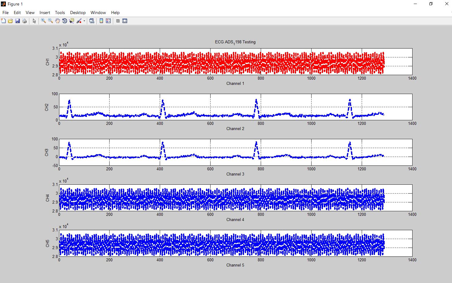
title('ECG ADS_1198 Testing');
ylabel('CH1');
subplot(312);
drawnow; 
plot(y2,'b--','linewidth',3)
grid on;
ylabel('CH2');

Here's a sample of the ECG signal I plotted out via Matlab, but it looks wierd.

I'm wonder Serial.print is too slow….., or channel data for process is wrong (every channel is 16 bits data with two complement)

Anyone who have experience about this, hope can give me more information, very thank you >< !
here is my email: frank613055@gmail.com

Any advise will be appreciated.
Frank

Hi:
If someone have experience about this, hope give some suggestion. very thank!

I'm working on an ECG-related project, using the TI ADS1198 with the Arduino. I've had success with writing/reading register by SPI bus (for example get ID Register value 182 for ads1198 & set every input channel to Normal electrode ).

I want to show channel via serial comport to MATLAB, but I got strange wave form like below picture.

I just show 5 channel firstly, channel 1,4,5 is odd( but i do make this channel in Normal electrode mode ), channel 2,3 seems correct ?

but not sure. So it is very confuse me why channel 2,3 seems can get data fine, but other can't.

Here is setting I write to ads1198 register,

1. Q: Am I wrong with this setting ?

Cuz I not much sure about the function from 0x0D to 0x19, just follow the register map table I saw in TI software for ADS1198 demo kit, it can see all channel wave correct.

void adsNormalElectrode()
{
  adc_wreg(0x01, 0x04);  //Config1 //0x04 500SPS
  adc_wreg(0x02, 0x10);  //Config2 //0x10
  adc_wreg(0x03, 0xDC); //Config3 //0xDC
  adc_wreg(0x04, 0x03);  //LOFF     //0x03
  adc_wreg(0x05, 0x00);  //CH1SET//0x00
  adc_wreg(0x06, 0x00);
  adc_wreg(0x07, 0x00);
  adc_wreg(0x08, 0x00);
  adc_wreg(0x09, 0x00);
  adc_wreg(0x0A, 0x00);
  adc_wreg(0x0B, 0x00);
  adc_wreg(0x0C, 0x00);  //CH8SET   //0x00

  adc_wreg(0x0D, 0x00);  //RLD_SENSP  //0x00
  adc_wreg(0x0E, 0x00);  //RLD_SENSN  //0x00  
  adc_wreg(0x0F, 0xFF);  //LOFF_SENSP //0xFF
  adc_wreg(0x10, 0x02);  //LOFF_SENSN //0x02
  adc_wreg(0x11, 0x00);  //LOFF_FLIP  //0x00
  adc_wreg(0x12, 0x00);  //LOFF_STATP //0x00
  adc_wreg(0x13, 0x00);  //LOFF_STATN //0x00
  adc_wreg(0x14, 0x00);  //GPIO       //0x00
  adc_wreg(0x15, 0x00);  //PACE       //0x00
  adc_wreg(0x16, 0x00);  //RESP       //0x00
  adc_wreg(0x17, 0x00);  //CONFIG4    //0x00
  adc_wreg(0x18, 0x00);  //WCT1       //0x00
  adc_wreg(0x19, 0x00);  //WCT2       //0x00
}

I put ads1198 in RDATAC Mode (0x10), and I check its wave form with Agilent logic analyzer, seems correct

I am sure I convert every channel 16bits data (in 2's complement binary) to decimal value and plot it in MATLAB.

The way I deal with 16 bits data in Matlab

s=serial('COM9','BaudRate',115200); % setup comport  fopen(s);  % Open comport 
T1=fread(s,1); //Get channel first  byte
T2=fread(s,1); //Get channel second byte
ch_1=T1*256+T2;//make it 16bits
change2dec=dec2bin(ch_1,16);
value_ch1 = twos2dec(change2dec);

Here is way I send every byte after I put ads1198 in RDATAC mode

int adc_read_data(void) //function to read in 5 channel of data
{
  int i = 0;
  digitalWrite(slaveSelectPin, LOW);
  //attempt to read in one channel only. 3 bytes of STATUS + 2 bytes of one channel data
  int numSerialBytes = 13;// now just read 5 channel to check
  unsigned char serialBytes[numSerialBytes];  
  for (i = 0; i < numSerialBytes; ++i)
  {
    serialBytes[i] = SPI.transfer(0);
  }
  delayMicroseconds(1);
  digitalWrite(slaveSelectPin, HIGH);

  for (i = 3 ; i < numSerialBytes; ++i)
  {
    Serial.write(serialBytes[i]);  //send byte to MATLAB
  }  
}

And this is environment I used: ECG Simulator , D15 cable, 60-80BPM, 1mV

Can one guide me what's problem for me to get data this result? how to fix it ?

Looking to your valuable suggestions, thanks in advance.

Best

Frank | frank613055@gmail.com

1 Like

@frank613055, please do not cross-post. Other thread removed.

@frank613055, please do not cross-post. Threads merged.