The problem i am facing is that as i approach the switch, before i reach it the led glows. As i move my hand away it stops glowing. Basically the set up works without me touching the switch.
Also at other times the setup works perfectly when i tap on the switch. But when i press it, it stops sensing change.
Why is this happening? Is it a problem with my board?
Your hand is making the pin pick up stray sugnals. Read about pinMode(x, INPUT_PULLUP) here.
Use that approach and change the wiring (which you didn't show) so that the switch connects the pin to ground not 5V. The pin will normally be high (via the pullup) and go low when you push it. Change the code to reflect that pushed is low and un-pushed is high.
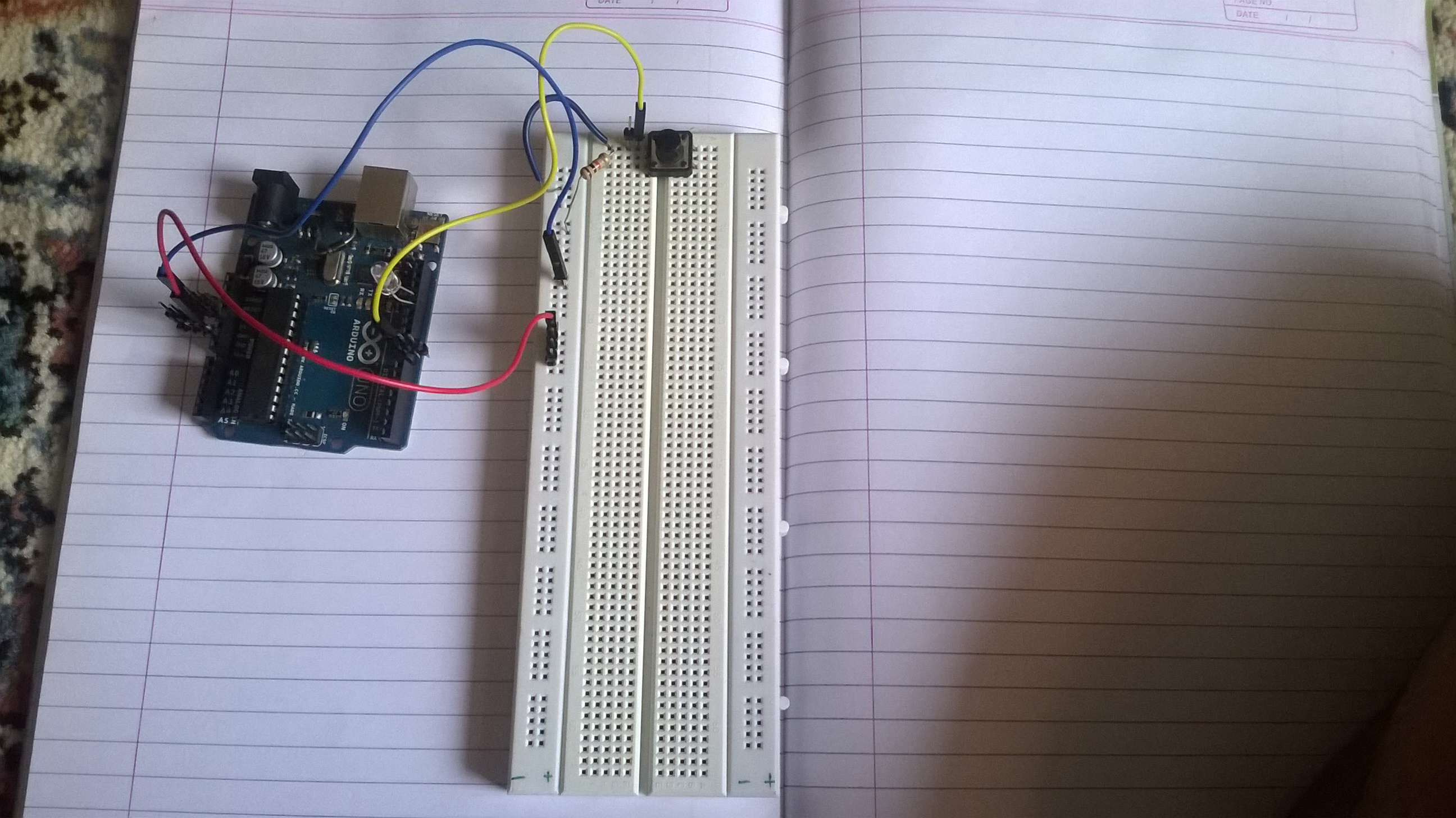
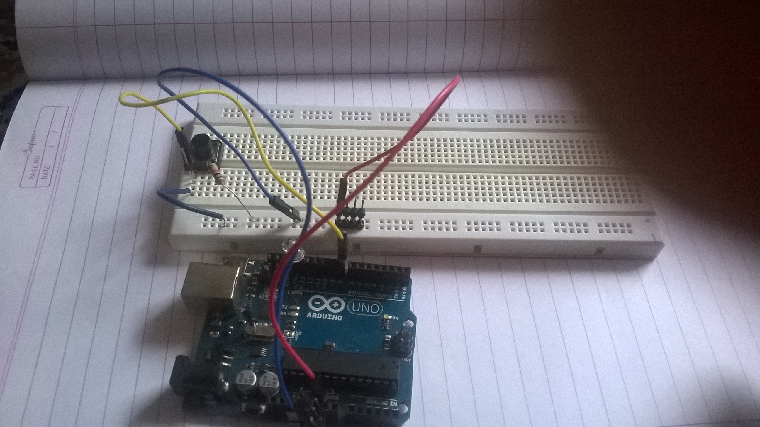
It's very difficult (ie impossible) to figure out your circuit from those pics- can you do a sketch of the circuit and post a photo of it for us?
But as far as I can see, you don't have a pullup resistor: you have a resistor in series with the switch and the pin. I'm not sure though, from the pix.
That said, it's MUCH easier to use the internal pullup, and have the pin high normally and to ground when pressed.
But if you post a pic of a circuit schematic, we'll see more clearly.
You seem to have only connected one side of the switch.
Tip - wire push buttons like this across a diagonal, then you always get the right two pins.
i am still facing the same problem. it works continuously 3 times , then doesnt work the next 3 times.
That was not the problem you posted originally you said:-
As i move my hand away it stops glowing. Basically the set up works without me touching the switch.
Also at other times the setup works perfectly when i tap on the switch. But when i press it, it stops sensing change.
Grumpy_Mike:
Tip - wire push buttons like this across a diagonal, then you always get the right two pins.
That IS a good tip... they always confuse me.
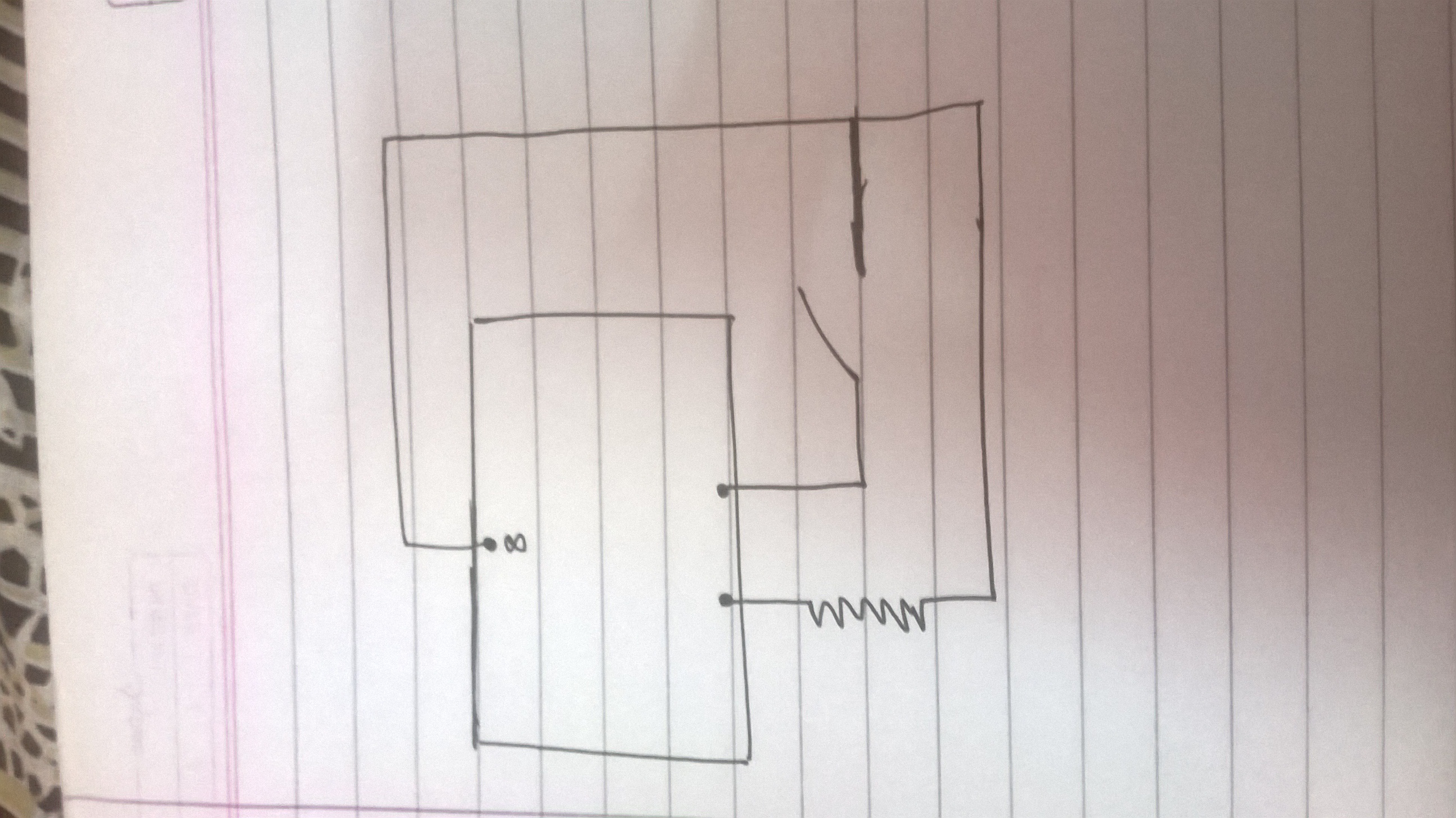
The diagram attached shows how those 4-pin switches work internally so you can see what Mike says makes sense. Pins on a diagonal are always across the switch; pins on one side might or might not be. Awesome tip....
fishfry:
the resistor that i connected is a pull up resistor. value 10k ohms.
I think you may the switch wired wrong: looks to me like 5V is connected to GND permanently through the resistor and you're not pulling the i/o pin to 5V.
Please do all of us- including yourself- a favour, and lose the external resistor. Use the INPUT_PULLUP approach and then just simply pull the i/o pin to ground through the switch as I suggested earlier, like this
fishfry:
the resistor that i connected is a pull up resistor. value 10k ohms.
A pull up resistor goes directly from the input pin to 5V. You do not have a resistor connected directly to the input pin you have it going through the switch.
The switch should be wired from the input and one end of the pull up resistor with the other end of the switch to ground.