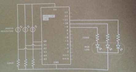
Hi everyone. I am trying to get a better understanding of the circuit in project 4. In particular, the part of the design I do not understand is the 10 kilo-ohm resistors which are plugged into the ground. I'm trying to visualize how the electricity is running through this circuit but I just don't understand those resistors. I feel very confident in my understanding of the circuits in the previous projects(where I feel I would be able to replicate the project without referencing the book), but I do not feel that way about this part of project 4.
The photoresistor and the 10K make a voltage divider which the Analog input reads.
Analog voltage= ~5V*10000/(photoresistor + 10000)
and
Analog Reading = ~Analog/5 * 1023
Without the 10K, the photoresistor just becomes a variable value pullup resistor that would read as 5V/1023 all the time.
Sorry, I'm a complete beginner with electronics and I don't really understand. This is the first time in the book I'm seeing one of these dividers. I think I understand the 5V*10000... 5 volts from the board, 10k from the resistor because Ohms law says volt s= current * resistence, but why are we dividing by (photoresistor + 10000)?
Again, I apologize if these questions seems silly, I've literally never worked on any sorts of electronics before. I am a programmer and my only experience with circuits are of the logical variety.
Ok, so V=IR, and V/R = I. Ohms Law.
There will a current flowing thru both resistors.
V/(photoresistor + 10000) = Itotal
The voltage across each resistor is then
V1= Itotal * photoresistor,
Vout = Itotal * 10000,
Vin = V1 +Vout
Put it all together, do some algebra, and you get
Vout = Vin * R2/(R1 +R2)
(and Vin = V1 + Vout, or Vin - Vout = V1)
R1 is the resistor between Vin and Vout (photoresistor), and R2 is the resistor between Vout and Gnd (10000).