Pots+piezo through multiplexer

I currently work on my first project - a midi controller. I need to read inputs from 8 potentiometers, 8 piezo buzzers and a couple of buttons. For that sake I used 2 multiplexers each one for pot or buzzers.
Potentiometers are meant to send a values to control sound parameters (volume), buzzers are for generating midi signal (each one is up to different midi note) with some velocity.

My problem is:

  1. I get inputs (changes of velocity) when I don't change the potentiometer's resistance. How can I make it stop sending all the same input?
  2. I can only read inputs from 1 analog pin (from 1 multiplexer). How can I read inputs from both multiplexers?
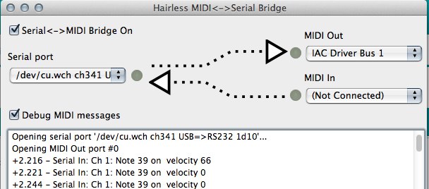
  3. When I hit one piezo, arduino sends a midi note with a proper velocity and not proper midi note (I'm hitting all the same piezo and it sends note 60, vel 30, note 64 vel 50). Maybe that's because I connected only one piezo to mux and grounded other mux inputs by 1m ohm resistors.
  4. Is there any way to express functioning of piezos (sending midi notes and velocities) and pots (sending only velocity value) in one function? If no, how can I adjust different parts of code to a different pins?

I use a clone of arduino uno (ch340g).

#define OUT_A 2
#define OUT_B 3
#define OUT_C 4

int lastVal = 0;
int piezo[8];
byte note[8] = {
  57,58,59,60,61,62,63,64};

int pin; 
int noteOn = 144;
int noteOff = 128;

int knock;
int threshold = 50;

boolean firstKnock;
int LED1 = 13;


void setup() {
  pinMode(OUT_A, OUTPUT);
  pinMode(OUT_B, OUTPUT);
  pinMode(OUT_C, OUTPUT);
  
  pinMode(LED1,OUTPUT);

  Serial.begin(57600);
}

void loop() {   
   for (int i = 0b000; i <= 0b111; i++) {
     digitalWrite(OUT_A, bitRead(i, 0));
     digitalWrite(OUT_B, bitRead(i, 1));
     digitalWrite(OUT_C, bitRead(i, 2));
  
  knock = analogRead(piezo[i]);
  if (knock>threshold){
    knock = (knock/8) - 1; 
    byte node = note[i];
 
    MIDImessage(noteOn, node, knock);
    delay(50);
    MIDImessage(noteOn, node, knock);
    delay(20);
  }
};
};
void MIDImessage(byte command, byte data1, byte data2) {
   Serial.write(command);
   Serial.write(data1);
   Serial.write(data2);
};
  1. I get inputs (changes of velocity) when I don't change the potentiometer's resistance. How can I make it stop sending all the same input?

Kep a track of the last reading you sent and only send a new one if it has changed by say more than 4.

if(abs(oldReading - newReading) > 4) { // send new data
  1. I can only read inputs from 1 analog pin (from 1 multiplexer). How can I read inputs from both multiplexers?

We need to see your schematic before we can answer that.

and grounded other mux inputs by 1m ohm resistors.

Way too high you need a 10K impedance to be able to scan a multiplexer, including the one inside the Arduino chip, successfully.

  1. don't understand the question. one function can do anything you write it to do.

Both of muxs are connected that way.
Also forgot to mention that I use 4051 mux

Grumpy_Mike:
4) don't understand the question. one function can do anything you write it to do.

I have a function ' MIDImessage(noteOn, note, velocity) '
Pots need to change velocity and not change a note
Piezos need to change a note (according to the dependance on the piezo that is being used) and the velocity.
How can I express that? Is there any way to say:
'if (AnalogPin = 0) {do pot code} else if (AnalogPin = 1) {do piezo code)' ?

Thanks but I was expecting a schematic of what you had, not a physical layout diagram of half of what you have.

You have a lot wrong with your code. For example

knock = analogRead(piezo[i]);

is using an uninitialised array to define the pin number. This should be just

knock = analogRead(0);

You don't put a colon after a brace.

I changed my code according to this topic.

The problem is whenever I hit any piezo, it sends the 8th note (the last note from PadNote array) or sometimes any random note from the array. Is that because I don't use a ceramic capacitor?

Also attached the schematic. I highly apologize for this mess, but for now I don't have anything else.

unsigned char PadNote[8] = {30,34,26,24,33,31,29,39};
unsigned char status;
int PadCutOff[8] = {200,200,200,200,200,200,200,250};   //not using this right now
int MaxPlayTime[8] = {25,25,25,25,25,25,25,25};        
#define  midichannel 0;                 
boolean activePad[8] = {0,0,0,0,0,0,0,0};      
int PinPlayTime[8] = {0,0,0,0,0,0,0,0};             
boolean VelocityFlag  = true;
int pin = 0;
int hitavg = 0;
int pad = 0;
int r0 = 0;
int r1 = 0;
int r2 = 0;
int count = 0;
int multiplex[8];

void setup() 
{
  pinMode(2, OUTPUT);
  pinMode(3, OUTPUT);
  pinMode(4, OUTPUT);
  Serial.begin(57600);
}

void loop(){

  readSensors(0);
  checkSensors(0);
}
void readSensors (int analogPin) {
  for(count=0; count <= 7; count++)
  {
    r2 = bitRead(count,0);
    r1 = bitRead(count,1);
    r0 = bitRead(count,2);
    digitalWrite(2, r0);
    digitalWrite(3, r1);
    digitalWrite(4, r2);
    multiplex[count] = analogRead(0);
  }
}
  
void checkSensors (int analogPin)
{
  for(int pin=0; pin <=7; pin++)
  {
    hitavg = multiplex[pin];
    pad=pin;
   
    if(hitavg > 200)
    {
      if((activePad[pad] == false))
      {
        hitavg = map(hitavg,0,1023,50,127);
        MIDI_TX(144,PadNote[pad],hitavg);
        delay(5);
        MIDI_TX(144,PadNote[pad],0);
        PinPlayTime[pad] = 0;
        activePad[pad] = true;
      }
      else
      {
        PinPlayTime[pad] = PinPlayTime[pad] + 1;
      }
    }
    
    else if((activePad[pad] == true))
    {
      PinPlayTime[pad] = PinPlayTime[pad] + 1;
      if(PinPlayTime[pad] > MaxPlayTime[pad])
      {
       activePad[pad] = false;
       MIDI_TX(144,PadNote[pad],0);
     }
    }
  }
}

void MIDI_TX(unsigned char MESSAGE, unsigned char PITCH, unsigned char VELOCITY) {
  status = MESSAGE + midichannel;
  Serial.write(status);
  Serial.write(PITCH);
  Serial.write(VELOCITY);
}

Is that because I don't use a ceramic capacitor?

More than likely.
Also are you using 1K resistors most circuits use 1M also you have no capacitor across your sensor like other circuits.

Grumpy_Mike:
you have no capacitor across your sensor like other circuits.

What capacitor exactly do I need for piezos? Is 1 uF enough?

I connected a 1uF capacitor to Vcc and Gnd of the 4051 (using a jumper wire). However, I still get the same 8th note triggered

What capacitor exactly do I need for piezos? Is 1 uF enough?

No see this project.

Although the physical construction is crap.

And are you using 1M resistors?

Yes, I do use 1M ohm resistor for each piezo.
There is no capacitors in this project ;\

Grumpy_Mike:
you have no capacitor across your sensor like other circuits.

So what capacitors do you mean there? That are attached to a piezo?

I thought it was not capacitors attached to a piezos, but diods. Didn't get what are they for though

The diode is for shorting out the negitave transition from the piezos that can damage the Arduino or multiplex inputs. The capacitors are for holding the voltage that they produce to give the software time to get round to looking at that input.

For some reasons still doesn't work with a capacitor attached to positive and ground pins of 4051.
I receive 39 note triggered for most cases and rarely others (with no dependence on what note I want to trigger)
Seeking for help

 unsigned char PadNote[8] = {30,34,26,24,33,31,29,39};
unsigned char status;
int PadCutOff[8] = {200,200,200,200,200,200,200,250};   //not using this right now
int MaxPlayTime[8] = {25,25,25,25,25,25,25,25};        
#define  midichannel 0;                 
boolean activePad[8] = {0,0,0,0,0,0,0,0};      
int PinPlayTime[8] = {0,0,0,0,0,0,0,0};             
boolean VelocityFlag  = true;
int pin = 0;
int hitavg = 0;
int pad = 0;
int r0 = 0;
int r1 = 0;
int r2 = 0;
int count = 0;
int multiplex[8] = {0,1,2,3,4,5,6,7} ;

void setup() 
{
  pinMode(2, OUTPUT);
  pinMode(3, OUTPUT);
  pinMode(4, OUTPUT);
  Serial.begin(115200);
}

void loop(){

  readSensors(0);
  checkSensors(0);
}
void readSensors (int analogPin) {
  for(count=0; count <= 7; count++)
  {
    r2 = bitRead(count,0);
    r1 = bitRead(count,1);
    r0 = bitRead(count,2);
    digitalWrite(2, r0);
    digitalWrite(3, r1);
    digitalWrite(4, r2);
    multiplex[count] = analogRead(0);
  }
}
  
void checkSensors (int analogPin)
{
  for(int pin=0; pin <=7; pin++)
  {
    hitavg = multiplex[pin];
    pad=pin;
   
    if(hitavg > 200)
    {
      if((activePad[pad] == false))
      {
        hitavg = map(hitavg,0,1023,50,127);
        MIDI_TX(144,PadNote[pad],hitavg);
        delay(5);
        MIDI_TX(144,PadNote[pad],0);
        PinPlayTime[pad] = 0;
        activePad[pad] = true;
      }
      else
      {
        PinPlayTime[pad] = PinPlayTime[pad] + 1;
      }
    }
    
    else if((activePad[pad] == true))
    {
      PinPlayTime[pad] = PinPlayTime[pad] + 1;
      if(PinPlayTime[pad] > MaxPlayTime[pad])
      {
       activePad[pad] = false;
       MIDI_TX(144,PadNote[pad],0);
     }
    }
  }
}

void MIDI_TX(unsigned char MESSAGE, unsigned char PITCH, unsigned char VELOCITY) {
  status = MESSAGE + midichannel;
  Serial.write(status);
  Serial.write(PITCH);
  Serial.write(VELOCITY);
}

For some reasons still doesn't work with a capacitor attached to positive and ground pins of 4051.

Was it a ceramic capacitor? Were the leads cut as short as possible?

I think you need to post a picture of your actual circuit along with a schematic of what you have.

Why are you doing this

if((activePad[pad] == false))
      {
        hitavg = map(hitavg,0,1023,50,127);
        MIDI_TX(144,PadNote[pad],hitavg);
        delay(5);
        MIDI_TX(144,PadNote[pad],0);
        PinPlayTime[pad] = 0;
        activePad[pad] = true;
      }

Why? You are sending a note on followed just 5mS later with a note off. You are not going to here that as a note being played.