So I've been working on this board to light a prop and I was hoping I could get some feedback on my work.
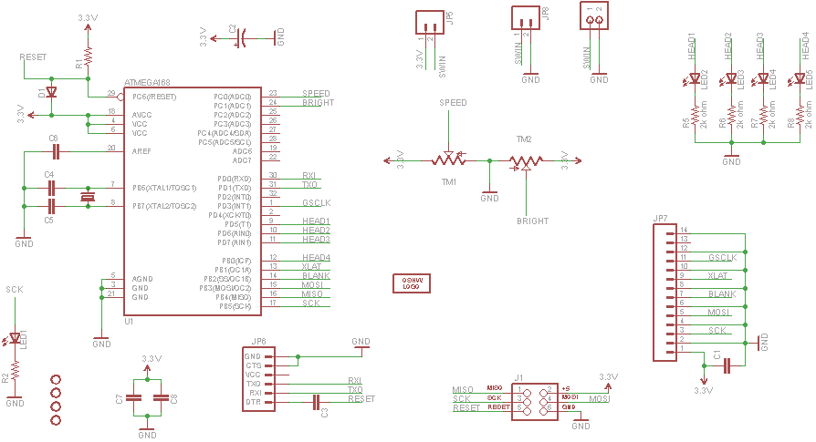
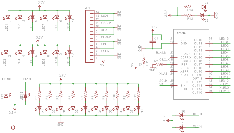
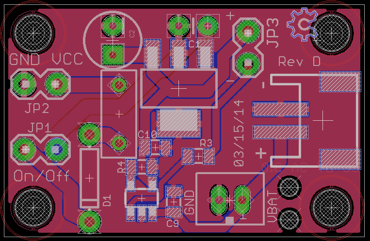
The "kit" has three (3) boards: A CPU board, a Driver board, and a power board. Attached are images of each board exported from Eagle.
The CPU and Driver board are connected, and the Power board is about 6" away (along with a Li Poly battery).
The odd mix of thru-hole and SMT is based on the contents of my parts drawers and nothing else to note. Though I have yet to use any of the SMT TI LED driver chips.
I've done several revisions of these boards and everything seems to work fine (of course I am just blinking LEDs at random) but before I order 50 PCBs I thought it might not hurt to have other eyes take a quick peek.
Anything I did wrong or should do differently? And on the CPU board I added C1 and C2 specifically to help prevent any noise problems. Are they really helping or am I just wasting my money (C2 is $1 even at quantity 25)?
Do they have their own power supply separate from the processor's power supply?
No. I should have mentioned this board is running at 8Mhz and both the CPU and driver board are being powered directly by the Li Poly battery connected to the Power board.
If you follow the TLC5940 datasheet to the letter, the connected LEDs should have a forward voltage <= 2.3 (the voltage drop through the LED driver is supposed to be >= 1). Is the forward voltage <= 2.3?
I routinely operate the TLC5940 / DIP with it dropping about 0.5 volts (violating the specifications). I have not had any problems. I have no what happens at the failure point. My guess is the current cannot be controlled resulting in a fault on that channel.
3.7 - 3.5 = 0.2 volts. I guess you're going to find out how the chip behaves.
I have a similar board that has worked flawlessly (three copies; used daily for several months). Some highlights are below that will hopefully help. I can't find any reason your boards won't work.
• One 5 volt power supply for everything (excellent quality switching wall wart)
• 30 mA per channel
• All sixteen channels used
• Two LEDs per channel; Vf = 2.1; drop through the TLC5940 is 0.8 volts. I have tested on a breadboard with a drop of about 0.5 volts.
• 0.1 uF across VCC and GND as close as possible to the TLC5940. This capacitor is required. The circuit is unstable without it. Apparently, the TLC5940 generates a lot of switching noise on the control side.
• 47 uF on the LED side of the circuit
• ATtiny84; 0.1 uF across VCC and GND as close as possible to the processor
• The board is split so the PWM lines are isolated in one section, the communications lines are in a middle section, and the analog input lines for the t84 are in a third section. The analog inputs have not required averaging / software filtering. There is no hardware filtering beyond the 0.1 uF for the processor.
• The TLC5940 clock is driven from CLKO on the t84. At 8 MHz the PWM frequency is 1953. Even with the board in motion there is no flickering or shearing. I believe the setup would work for a POV display.
• The board is programmed via ISP. To protect the TLC5940 there are 51K series resistors on the SPI lines.
• There are some pullup and pulldown resistors on various control lines (like RESET on the t84)
Note about the TLC5940: It supposedly is capable of returning status information to the processor. I have never gotten that to work. In other words, I have found no reason to connect serial out back to the processor. (Your schematic shows it not connected.)
'fraid so. Will need to do some testing but I believe that the battery life will be acceptable in this case. If not I can always try a different power board.
I appreciate your advice. You've given me quite a bit to think about.