I'm making a project in which two Arduino UNO are communicating via RF through the nrf24L01 modules. As I said, I have two Arduino UNO, a 1uF capacitor between GND-VCC on each module, an external power supply that gives 220VAC -- 3.3V 1A and I have used both popular libraries: TMR2h nrF24 an the normal one RF24-Master.
I'm not even trying to send/receive data because on the printDetails() I can clearly see that no addresses are given correctly due to it's values are fixed to 0x00 or even 0xff. As I read in a lot of forums It's suposed to be a pin connection but no way I tested and checked it many times. I'm a bit desperate because I've spent a lot of hours here and have no idea what else to check.
NOTE :
Initally I was following the tutorial 1-Day Project: Arduino and nRF24L01+ Data Transceiver - YouTube by Julian Ilett (I have the exactly the same connection pinout). The code I tested is the same in the video (the Joystick receiver/transmitter) but as long as It wasn't working I continued trying with basic example tests:
hi,
if you have a chinese module you must use an extern alimentaion .you need a 3.3 v linaer regulator as :
-AMS 1117 ,
-2000uf and 1000uf capacitors
the first between Vin and ground and the second between the Vout and ground .
I said you again don't test your nrf with sketh like a getting started ,if you want really know if your module work use the pratic test (boton and led)
I followed your tutorial earlier but now I've read it again and do it all again. Trying the SimpleTx/Rx.ino example the only thing I can see in output is: [SimpleRx Starting
]
alomar1997:
I followed your tutorial earlier but now I've read it again and do it all again. Trying the SimpleTx/Rx.ino example the only thing I can see in output is: [SimpleRx Starting
Post the actual code that YOU have uploaded to your two Arduinos and also post a photo of a pencil drawing showing how you have everything connected.
Post a sample of the output from both Arduinos.
Exactly what Arduinos are you using? Some of them don't have enough 3.3v power
Have you got 10µF capacitors across Vcc and GND for the nRF24s
Are you using nRF24s with the PCB antenna or the high-power version with the external antenna?
Sorry, here you have the schematic attached. When it refers to the code it is the on you give me.
TX
// SimpleTx - the master or the transmitter

#include <SPI.h>
#include <nRF24L01.h>
#include <RF24.h>


#define CE_PIN   9
#define CSN_PIN 10

const byte slaveAddress[5] = {'R','x','A','A','A'};


RF24 radio(CE_PIN, CSN_PIN); // Create a Radio

char dataToSend[10] = "Message 0";
char txNum = '0';


unsigned long currentMillis;
unsigned long prevMillis;
unsigned long txIntervalMillis = 1000; // send once per second


void setup() {

    Serial.begin(9600);

    Serial.println("SimpleTx Starting");

    radio.begin();
    radio.setDataRate( RF24_250KBPS );
    radio.setRetries(3,5); // delay, count
    radio.openWritingPipe(slaveAddress);
}

//====================

void loop() {
    currentMillis = millis();
    if (currentMillis - prevMillis >= txIntervalMillis) {
        send();
        prevMillis = millis();
    }
}

//====================

void send() {

    bool rslt;
    rslt = radio.write( &dataToSend, sizeof(dataToSend) );
        // Always use sizeof() as it gives the size as the number of bytes.
        // For example if dataToSend was an int sizeof() would correctly return 2

    Serial.print("Data Sent ");
    Serial.print(dataToSend);
    if (rslt) {
        Serial.println("  Acknowledge received");
        updateMessage();
    }
    else {
        Serial.println("  Tx failed");
    }
}

//================

void updateMessage() {
        // so you can see that new data is being sent
    txNum += 1;
    if (txNum > '9') {
        txNum = '0';
    }
    dataToSend[8] = txNum;
}
RX
// SimpleRx - the slave or the receiver

#include <SPI.h>
#include <nRF24L01.h>
#include <RF24.h>

#define CE_PIN   9
#define CSN_PIN 10

const byte thisSlaveAddress[5] = {'R','x','A','A','A'};

RF24 radio(CE_PIN, CSN_PIN);

char dataReceived[10]; // this must match dataToSend in the TX
bool newData = false;

//===========

void setup() {

    Serial.begin(9600);

    Serial.println("SimpleRx Starting");
    radio.begin();
    radio.setDataRate( RF24_250KBPS );
    radio.openReadingPipe(1, thisSlaveAddress);
    radio.startListening();
}

//=============

void loop() {
    getData();
    showData();
}

//==============

void getData() {
    if ( radio.available() ) {
        radio.read( &dataReceived, sizeof(dataReceived) );
        newData = true;
    }
}

void showData() {
    if (newData == true) {
        Serial.print("Data received ");
        Serial.println(dataReceived);
        newData = false;
    }
}
Now I have a stable power supply that gives me 3.3V- 800mA.
Trying the same code that I posted on post #9 I have on the output serial something like
Data received
Data received
Data received ⸮
Data received
Data received
Data received
Data received ⸮
Data received ⸮
Data received
Data received ⸮
Data received
Data received
Data received
Data received
Data received
Data received
Data received
Data received
Data received
Data received ⸮
Data received ⸮
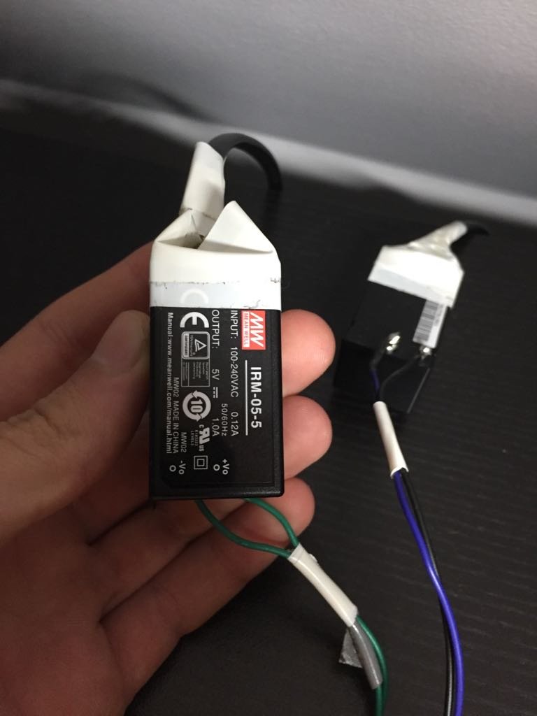
I get data now but it's not readable at all. I'm attaching some pictures of the new power supply circuit. I have also added a 10uF capacitor on each nRF.
Data Sent Message 0  Acknowledge received
Data Sent Message 1  Acknowledge received
Data Sent Message 2  Acknowledge received
Data Sent Message 3  Acknowledge received
Data Sent Message 4  Acknowledge received
Data Sent Message 5  Acknowledge received
Data Sent Message 6  Acknowledge received
Data Sent Message 7  Acknowledge received
Data Sent Message 8  Acknowledge received
Data Sent Message 9  Acknowledge received
Data Sent Message 0  Acknowledge received
Data Sent Message 1  Acknowledge received
once per second, in the RX one I see what I said but on a ultra high speed, not once per second. Robin2, can you deduce what's happening as it is a familiar code to you.
What happens if you de-power the receiver (Arduino and nRF24) and the power them on again to make sure that the nRF24 resets?
In fact do that for both Arduinos.
I have seen that very fast output in some of my tests but I can't remember what caused it - although it clearly was not because of data properly received. Is suspect you will get that output from the Rx even when the TX is off. I think it was sorted out by de-powering everything and getting the nRF24 to reset properly. Unfortunately the nRF24 does not have reset instruction or a reset pin.
Yeah, I got two separate power supplies for each nRF. As you said, I disconnected both Arduinos from USB, and also the power supplies from 220V AC, reseted and uploaded both codes again and it seems that the same is happening.
I tried to move and touch while sending/transmitting all the pins from both Arduinos and it seems that data is changing. Now I'm having things like:
Data received p
Data received p
Data received ⸮
Data received
Data received p
Data received p
Data received
Data received
Data received p
Data received ⸮
Data received
Data received P
Data received 0
I don't know what else it can be. I checked GetStarted examples and it seems that both nRFs get a normal address code. What would you try? I'm open to any suggestion or supposition that you could have as I'm trying to solve this ASAP. Let me know all you could need please.