I was wondering if you guys might be able to give me any tips.
I have been trying to run an Atmega328p on a breadboard. I've spent all day on this with no luck.
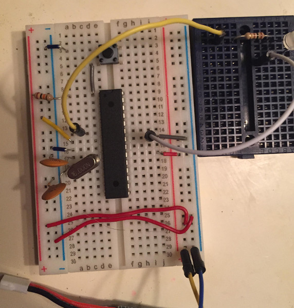
I've built this circuit on 3 different types of breadboards in case I wasn't getting a good connection. I have also tried the circuit without the button.
My breadboard design doesn't seem to be working for anything I try. I first started out wiring up my Pololu AVR Programmer v2 and trying to program a bootloader using AVR Dude. I then wired the breadboard up to my Arduino Uno and tried programming it. Both times I got errors saying device was not recognized. I finally discovered that I can plug the Atmega directly into the Arduino DIP and plug my AVR Programmer into the ICSP port on the Arduino. I then used Avrdude to program the bootloader. Woo hoo! I finally got a bootloader and can program using the Arduino IDE.
I uploaded a simple blink sketch which blinks an LED on PD4 of the microcontroller. I can touch the actual pin of the microcontroller when its plugged into the Arduino Uno board and the LED will blink.
So now I want to get this working on my breadboard. I unplugged the Atmega from the Arduino board and placed it on my breadboard. When I power it up(I know it's getting power), the LED will not blink when I touch it to port PD4.
I'm using a 16mhz crystal, 10k ohm resistor for reset, and 2 .1uf capacitors. I have tried switching all of these out with other components I have just in case something was bad.
I still can't get an LED blinking or use my breadboard for programming.
Any suggestions? It's really frustrating me. I can get an Attiny85 up and running on a breadboard in minutes by itself. I can see the Atmega is more complicated with the bootloader and everything.
merdenoms:
Thank you, I'll order some. Could they be anything greater like 100uf?
The ones on the crystal need to be 22pF and nothing else. The decoupling caps you have a little wiggle room on the size. But the ones on the crystal need to be 22pF for the crystal to work right.
Delta_G:
The ones on the crystal need to be 22pF and nothing else. The decoupling caps you have a little wiggle room on the size. But the ones on the crystal need to be 22pF for the crystal to work right.
I found some 22pf caps and tried those out. I'm not having luck with those either.
I got them with a cheap electronics kit on Amazon. The label on the kit also says they are 22pF Ceramic Caps.
Does it matter that they are ceramic? Maybe they aren't very good quality and aren't exactly 22pF.
Try remove crystal and apply external clock to XTAL1 pin. This way you know it is fault of the crystal. I think 22pF value is not so critical - 16 or 24 would probably work too.
Decoupling caps should be in order of 100nF (0.1uF) ceramic.
Smajdalf:
Try remove crystal and apply external clock to XTAL1 pin. This way you know it is fault of the crystal. I think 22pF value is not so critical - 16 or 24 would probably work too.
Decoupling caps should be in order of 100nF (0.1uF) ceramic.
Sorry, I'm kind of new to this. Do I use an Avrdude command to set that pin which is PB6 to external clock?
I am using .1uf caps for decoupling. I tried it without them as well. I also have a second 16Mhz crystal that I've tried but that doesn't help.
larryd:
PD4 is D04, is that what is in your sketch?
Make sure your LED is wired correctly.
Make sure you are using pins 9 and 10 for the crystal and the caps are not shorting out on the crystals case.
.
I used the default pin 13 in the Arduino sketch. When the Atmega was plugged into the Arduino board, I noticed that I could blink the LED by touching it to PD4. Let me double check that and try some other pins.