I am quite new at schematic drawings for electronics and i would like hopefully some people who are good at to provide me with some tips and guidance. I will post my latest schematic here (yes it was made with Fritzing, hopefully you can still help, without telling me to change software yet). This is quite new to me, and I look at it and realise, there must be a better way to do it. ie: standard placings, wire routing conventions, should i use different colours etc? any advise is greatly appreciated. This circuit is basically for a breakout board for a Mega. it has seperate 5, 12 and 24V supplies to the board. 5Volts for the Mega, 12Volts to feed the relay board and 24V to power the existing 24 switches.
Thanks
Adam

Download the free version of Eagle.
Spend a few days pulling hairs.
Then you can design whatever you want, and share with others.
And send the files to any circuit board manufacturer.
There are also many Arduino Eagle files online that you can use and mod.
The diagram is very confusing (to me).
Optos normally don't have the base connected, just collector and emitter.
LED current limiting resistor values are too low (220ohm on a 24volt supply is 100mA).
Leo..
Optos normally don't have the base connected,
Normally yes, but for frequency response you add a higher valued resistor to ground.
While that diagram is one of the better ones I have seen from Fritzing it is still very bad.
First off are the lack of labels, especially all that stuff at the bottom of the page, I have no idea what that means. Connections plugs and sockets should have each connection labeled so you know what they are.
Next the opto couplers need to be rotated by 90o to the left, and as mentioned they are wired up wrong.
Line crossing should be minimised, look for example at F5, if you swap over the connections then the wire from it would not have to make a crossing. Same for D3 if it were placed above R11 then that wire to it would not have to cross anything. This is simply poor layout of the components and results in a tangle of wiring that is very hard to read.
The aim of a schematic is to convey the circuit in a simple to read layout.
There are some general rules that also help and while not being too strict about them you will produce a more clear diagram if you pay attention to them.
- Positive at the top and ground at the bottom.
- Inputs on the left, outputs on the right.
There is also a lot wrong with the left hand side you seem to have connected a 24V supply to a 12V supply only with a diode!
I'm not familiar with Fritzing, but in general I'd suggest...
Keep all signal lines horizontal or vertical.
Avoid unnecessary step changes from one to the other (top right looks very messy).
Space the diagram out (this can help to align things to reduce stepping).
Make sure there's a clear demarcation between the component and a connecting signal line (make component outlines much thicker for example).
Colour is unneccesary in a well drawn circuit diagram.
Don't overlap / cross components with signals.
Hope that helps!
Hi,
A good effort with fritzy, but as Grumpy_Mike has said, it lacks numbering etc.
You might also like to try ExpressPCB, it has a good schematic editor, is not very big, is basic and does not have high overheads.
http://www.expresspcb.com/free-cad-software/
Tom..... ![]()
Or KiCad ![]()
The problem with a dedicated drawing package is that most times it does not have the right symbol and a newcomer is too inexperienced to draw the right one. This results in substitute symbols being used which are even more confusing.
I would recommend just a simple 2D vector drawing package.
TomGeorge:
You might also like to try ExpressPCB, it has a good schematic editor, is not very big, is basic and does not have high overheads.
It will also run under Linux using Wine.
Russell.
And make liberal use of the ground symbol, and Vcc nodes.
Check my signature for a couple of links. The key to a schematic is clarity.
Can anyone recommend a reasonably good (and preferably free) schematics application that will run on OS X?
Eagle Redirect Notice
Start with it after you figure how to get the parts in it it's down hill all the way.
It's by far the best out there. And the free one can do a lot after all not many people need boards bigger then it let's you draw and you'd have to take out a loan to buy a one time big board lol.
Thanks. I have Eagle and am starting what is looking to be a painful process of learning how to use it. I was thinking there might be another application just for drawing schematics. For example, I have used the free app on the digikey website. It's not great but it's straightforward.
Post 5 list the easiest to use sch software there is and it has great part list and is easy to make a part.
It works with wine on a mac.
But I hated eagle there's like tons of how to get started with it everyone leaves the main bit's an pieces out.
But after you get the hang of it really good adding the parts was the hard part for me but after that it was down hill run.
After all they should make it easier to load the parts you have 100 library files and can't pick a part without adding them first. Looks like it would just load them from the folder you put them in.
Or KiCad, open source alternative. It's becoming better and better.
septillion:
Or KiCad, open source alternative. It's becoming better and better.
I have used KiCad and can vouch for that comment.
But the problem remains with any package of how to find the correct symbol. That is why I think a general draw package is easier for hobby use. You can copy symbols you have used before or just draw new ones. This is especially important when you want to change the order of the pinout on an IC to make the schematic look cleaner and avoid all those unnecessary lines crossing.
I have barely ever made a symbol. Sometimes I edit one but most of the times I don't need to. That's because of the enormous amount of symbols and footprints this guy made. As well as the KiCad GitHub.
I have found Diptrace much simpler to learn than Eagle, and have already created a component in it.
It comes in Windows, Linux, and OSX versions. Free for noncommercial use, PCBs are limited to 500 pins. Email them and they will send you and upgrade to a 1000 pin limit.
Better to learn a schematic package that will also allow you to make PCBs in the future.
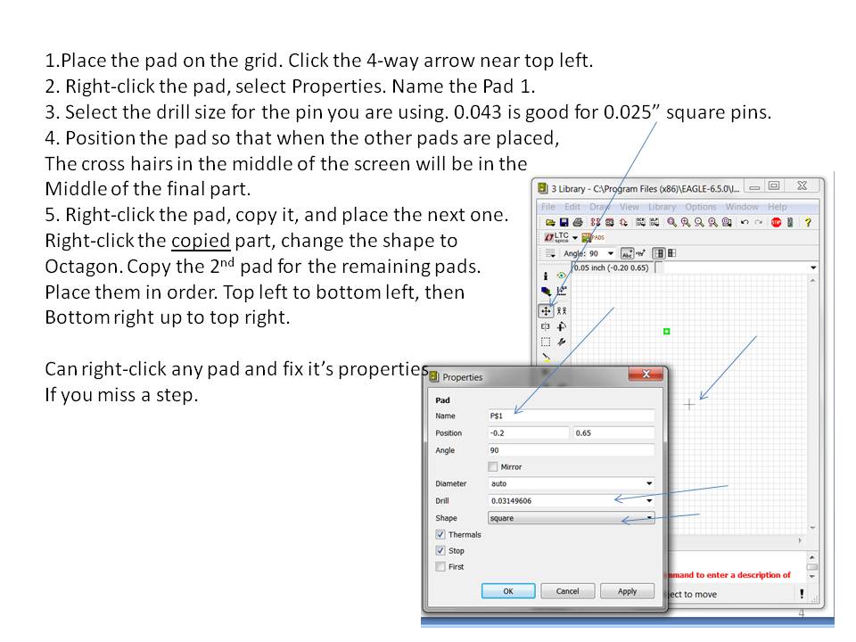
I created a set of slides for creating symbols in Eagle. It's not that hard once you do it a few times.
- Create the mechanical footprint. (pads & outline)
- Create the schematic symbol.
- Marry the 2 together.


I found it very frustrating to try to use fritzing to draw "nice" schematics; it was FAR too difficult to "neaten" a rough diagram... There are similar problems with many generic "drawing" packages; when you attach signals to a part on a schematic, you want there to be an actual "attachment" that isn't changed simply by moving the art and/or the wires...