MPU 6050 and RTC *Together*

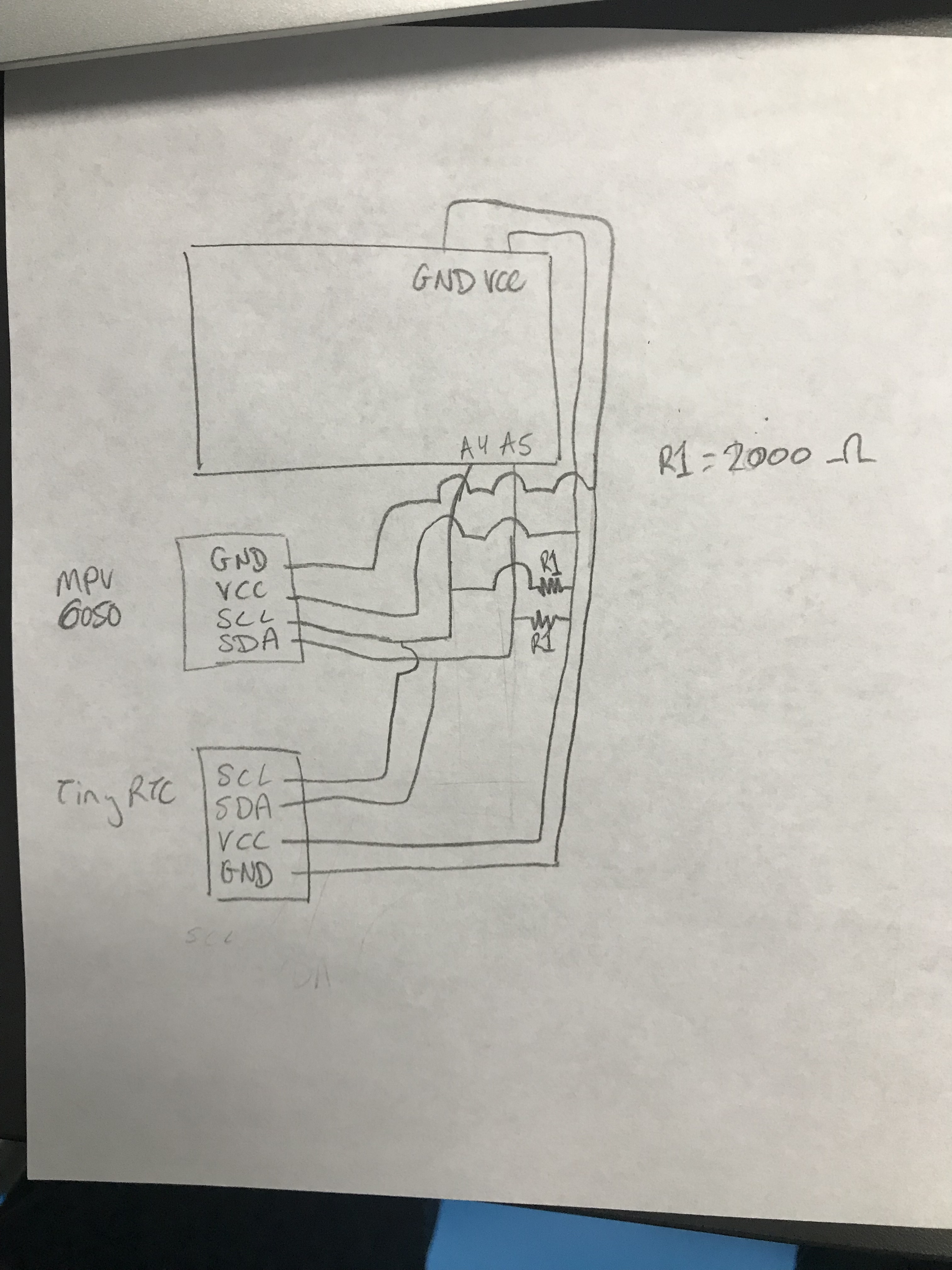
Hey! We are trying to use an MPU 9250/6500 and an RTC module with one Arduino. We are using the Analog 4 and 5 ports for I2C connection, but we also want to use their associated libraries (we found online). They both work separately, but when tied together with a pull-up resistor, they don't work at all. We have found no solution online to work so far... Any advice would be appreciated as we need both components for our project.

Thanks,
Engineering students with a dream

#include <MPU6050_tockn.h>
#include <Wire.h>
#include "RTClib.h"
RTC_DS1307 RTC;

MPU6050 mpu6050(Wire);

void setup() {
  Serial.begin(9600);
  Wire.begin();
  Serial.print("START==============================================");
//  Wire.beginTransmission(0x68);
//  Wire.beginTransmission(0x50);
  
  mpu6050.begin();
  RTC.begin();
  mpu6050.calcGyroOffsets(true);

  if (! RTC.isrunning()) {
    Serial.println("RTC is NOT running!");
    // following line sets the RTC to the date & time this sketch was compiled
    RTC.adjust(DateTime(__DATE__, __TIME__));
  }
  
}

void loop() {
  mpu6050.update();
//  Serial.print("angleX : ");
//  Serial.print(mpu6050.getAngleX());
  Serial.print("\tangleY : ");
  Serial.print(mpu6050.getAngleY());
//  Serial.print("\tangleZ : ");
//  Serial.println(mpu6050.getAngleZ());

  DateTime now = RTC.now(); 
        Serial.print("\t\t\t");
    Serial.print(now.year(), DEC);
    Serial.print('/');
    Serial.print(now.month(), DEC);
    Serial.print('/');
    Serial.print(now.day(), DEC);
    Serial.print(' ');
    Serial.print(now.hour(), DEC);
    Serial.print(':');
    Serial.print(now.minute(), DEC);
    Serial.print(':');
    Serial.print(now.second(), DEC);
    Serial.println(); 
}

but when tied together with a pull-up resistor,

What does this mean? Please post a complete wiring diagram (hand drawn is fine, but Fritzing is not).

Below is what you should be doing, although you may need pullups lower than 10K.

Note that all devices must run at the same voltage as the processor, if not use level shifters (which means your 3.3V MPU6050 module requires level shifters to work with a 5V processor).

Also if the connection is correct and they work separately in software but don't work together, its likely something in one of the libraries where they initialize the I2C. Have you checked if the addresses are configured properly as well?

@OP

It is most likely that the I2C addresses are conflicting:

MPU6050 Module address is 0x68 by default in my MPU6050.h Library
DS3231 Module address is also 0x68

What I did is this:
I edited the MPU6050.h Library and had set the address to 0x69, and then I have connected the AD0-pin of MPU6050 Module at 5V.

Thank you all for responding! I looked in the libraries and I can't find where to change the number to 0x69.

I attached a schematic - we are using two 1,000 Ohm resistors in series to get the 2k Ohms.

Thanks,
Noah

Does your MPU6050 module have 5V to 3.3V level shifters? Post a link to the product page.

pumpkin1119:
Thank you all for responding! I looked in the libraries and I can't find where to change the number to 0x69.

It is here:

Procedures:
Notepad++ -->C:-->Program Files --> users --> GM --> Documents -->Arduino-->libraries-->
Arduino-MPU6050-master--->MPU6050.h (open the file, change 0x68 to 0x69, save and exit).