I have an LED connected to GPIO pin 18. I can use the following Python code (running locally on the Pi) to make the LED turn on and off:
import RPi.GPIO as GPIO
import time
GPIO.setmode(GPIO.BCM)
GPIO.setwarnings(False)
GPIO.setup(18,GPIO.OUT)
print "LED on"
GPIO.output(18,GPIO.HIGH)
time.sleep(1)
print "LED off"
GPIO.output(18,GPIO.LOW)
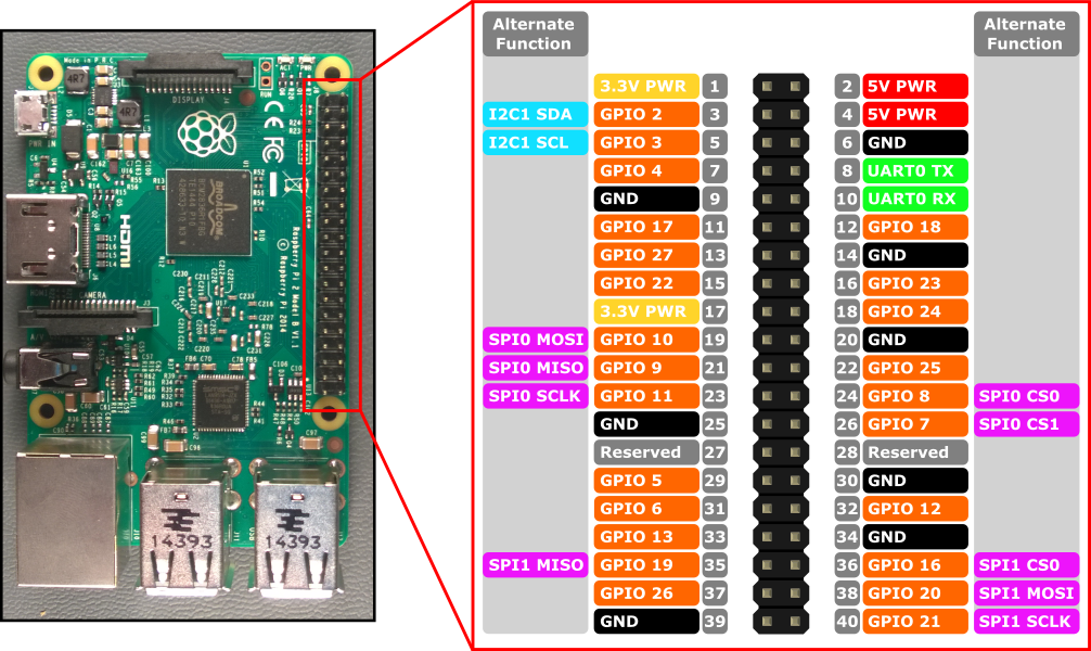
Note that it addresses GPIO pin 18. On the diagram this is the sixth pin on the second row.
Arduino Create doesn't refer to this pin as pin 18. No! It refers to it as pin 12. Here is a modified version of the example Blink sketch which makes that same LED blink on and off:
int MYLED = 12;

// the setup function runs once when you press reset or power the board
void setup() {
  // initialize digital pin LED_BUILTIN as an output.
  pinMode(MYLED, OUTPUT);
}

// the loop function runs over and over again forever
void loop() {
  digitalWrite(MYLED, HIGH);   // turn the LED on (HIGH is the voltage level)
  delay(2000);                       // wait for a second
  digitalWrite(MYLED, LOW);    // turn the LED off by making the voltage LOW
  delay(1000);                       // wait for a second
}
Arduino don't seem to have created any tutorials yet (04/04/2018) to help people using Arduino Create to program a Raspberry Pi so I have to thank Microsoft for providing the image above, which led me to solving this conundrum.
I think the following link has the same info as the graphic but we shouldn't have to reverse engineer this stuff from github. Similar pages exist for beaglebone and banana pi. Still waiting for docs and examples from Arduino.
A tip for voltage leveling between 3.3V and 5V devices, use 74HC4050 Hex Buffers.
They're cheap considering that 1 chip levels 6 lines of 5V down to 3.3V in a small package that could be built into a patch cable. An SPI bus only needs 3 lines leveled, would RPI ever run 2 SPI channels to 5V devices? One end on the RPi and two ends for 5V SPI?
The Arduino Create for Raspberry Pi builds Linux executables which are downloaded to Raspberry Pis running Raspbian Linux. It might work for other versions of Linux but I think only Raspbian is supported. Create also supports BeagleBone and Intel CPUs running Linux.
The "sketch" runs as root but is otherwise a regular Linux program. I do not see any option for a bare metal/no OS mode. It is possible to run more than one sketch at the same time.
As an alternative, it is pretty easy to build code to access the Pi GPIO, I2C, and SPI using the wiringPi library and gcc/g++. No need for a Cloud server to generate code when the Pi can run gcc/g++. In addition, there are wrappers for Python, Perl, Ruby, Java, nodejs, etc.