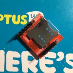
Recently I obtained a cheap (under $8) teeny-tiny SIM800 breakout board. The serial UART interfaced SIM800 makes it very easy for any embedded system to add cellular network access and connect to the cloud.
After some efforts, I managed to make it work with an Arduino Leonardo. Basically 5 wires are needed to connect the module to Arduino and they connect pins of VCC/GND/Rx/Tx/Reset. This is quite straight-forward.
My target is continuously sending HTTP requests containing sensor data to a web server (data as URL argument) and retrieve the response containing command. To make it easier for myself and other people who use the same SIM800 based modules, I started to write an Arduino library for this purpose. It contains only what I need at the moment. That includes what is needed to perform HTTP request and retrieving GSM location data. I am expanding it graudually over the next a few weeks. The library is hosted on GitHub and an exmple sketch is also available. The sketch can be as simple as following.
#include "SIM800.h"

#define APN "connect"
#define con Serial
static const char* url = "http://arduinodev.com/datetime.php";

CGPRS_SIM800 gprs;

void setup()
{
  con.begin(9600);
  while (!con);

  for (;;) {
    con.print("Resetting...");
    while (!gprs.init());
    con.println("OK");

    con.print("Setting up network...");
    byte ret = gprs.setup(APN);
    if (ret == 0)
      break;
    con.print("Error code:");
    con.println(ret);
  }
  con.println("OK");

  for (;;) {
    if (gprs.httpInit()) break;
    con.println(gprs.buffer);
    gprs.httpUninit();
    delay(1000);
  }
}

void loop()
{
  gprs.httpConnect(url);
  while (gprs.httpIsConnected() == 0) {
    // can do something here while waiting
  }
  if (gprs.httpState == HTTP_ERROR) {
    con.println("Connect error");
    return;
  }
  con.println();
  gprs.httpRead();
  int ret;
  while ((ret = gprs.httpIsRead()) == 0) {
    // can do something here while waiting
  }
  if (gprs.httpState == HTTP_ERROR) {
    con.println("Read error");
    return;
  }

  // now we have received payload
  con.print("[Payload]");
  con.println(gprs.buffer);

  // show position
  GSM_LOCATION loc;
  if (gprs.getLocation(&loc)) {
    con.print("LAT:");
    con.print(loc.lat, 6);
    con.print(" LON:");
    con.print(loc.lon, 6);
    con.print(" TIME:");
    con.print(loc.hour);
    con.print(':');
    con.print(loc.minute);
    con.print(':');
    con.println(loc.second);
  }
}
I purchased one of these a few months back from China on e-bay for about £6. Read the datasheet thoroughly and when it arrived, I connected it to a 2amp 3.7volt lithium battery. Using several resisters I was able to get 2.8volts to the reset pin as required in the datasheet. Then using an FTDI usb interface and eventually a standard Uno and then eventually a mini pro running at 3.3 volts I was once able to receive anything being transmitted from the sim800 TX pin. I plug it in, the led starts flashing, eventually slowing.
I send it "AT to initiate the auto-baud setting to respond on 9600. I do not get an "OK," from the modules tx pin. However, I know it can accept commands because I can send it the command to switch off. However, it switches itself back on in approximately 40 seconds. I can also call the sim with my phone and it rings. The Ring pin changes it's state when I dial it so I know the module is functioning.
I assumed it was defective so I purchased another one and today after waiting 20 days for it to arrive, I get the same thing. This time however, the TX pin simply mirrors the input that I send it's RX pin. Nothing coming over on the TX pin.
On top of that, I'm a little annoyed to find your posting lacking in detail. All you say about connecting the unit up is,
"After some efforts, I managed to make it work with an Arduino Leonardo. Basically 5 wires are needed to connect the module to Arduino and they connect pins of VCC/GND/Rx/Tx/Reset. This is quite straight-forward."
You would think so huh? Why did you use the unorthodox Leonardo? Did you try other boards to begin with and have no luck? Also, your pictures are lacking the use of "diodes," to alter the voltage. It looks like you're sending your Leonardo pins directly to the unit without interference. Are you doing anything special with your RX and TX lines? Are you pulling them up or down with a 10k resister perhaps? What am I missing?
I have one of these running on a Freetronics Ethermega. I am only using it to send and receive sms text messages.
The reset pin on these run at 2.8 volts output - you do not supply 2.8 volts to the reset pin. You ground the reset pin momentarily to do a hard reset on these devices.
I confirm you need a separate about 4 volt, 2 amp power supply. A 5 volt power supply may destroy these units. Without 2 amps these units cannot connect to a gsm network.
I get this compiling error with your lib? Do I need additional libs?
In file included from GPRSTest.ino:8:
C:\Program Files\Arduino\libraries\SIM800/SIM800.h: In member function 'bool CGPRS_SIM800::available()':
C:\Program Files\Arduino\libraries\SIM800/SIM800.h:79: error: 'Serial1' was not declared in this scope
Are you powering SIM800 with 4V? I had something like that because i forgot to add a diode to lower the voltage from 5V.
Also check your APN name, those messages showed are when code is trying to set APN.
And if using an external power source, don't forget to connect a common GROUND between power source and arduino
CatweazleNZ:
I have one of these running on a Freetronics Ethermega. I am only using it to send and receive sms text messages.
The reset pin on these run at 2.8 volts output - you do not supply 2.8 volts to the reset pin. You ground the reset pin momentarily to do a hard reset on these devices.
I confirm you need a separate about 4 volt, 2 amp power supply. A 5 volt power supply may destroy these units. Without 2 amps these units cannot connect to a gsm network.
Cheers
Catweazle NZ
using LM7805 connected to diode 1N4007, i managed to power up this module. but as you can say, i can't access anything related to SIM, such as AT+CNUM command, it will restart the module, i think it related to power shortage.
sahniana:
using LM7805 connected to diode 1N4007, i managed to power up this module. but as you can say, i can't access anything related to SIM, such as AT+CNUM command, it will restart the module, i think it related to power shortage.
7805 is grossly unsuitable for SIM800. SIM800 requires peak current of upto 2A while most 7805 in market these days provide a measly 300-400mA (as compared to theoretical 1A)..
you should try supplying power through a switching regulator like 2576 or LM2596.
Else, buy a SIM800 with onboard voltage regulator. SIM800 is a great GSM Modem and has been used to replace SIM900A by SIMCOM. if you are in India, I can suggest couple of places to buy GSM Online.
Hi guys! How are you connecting the reset pin to the Arduino? I'm using the same module, and I'm afraid to connect the reset of the module to a digital pin of the arduino to control it by software, because of the differences of the voltage. Should I put resistors in between this connection to lower the voltage?
Also is it normal, when I send the command AT+CPOWD to power off, it turns on after some seconds?
Is there a way to turn on the module with AT commands?
I have one SIM800 connected to arduino nano, running for days sending data every hour. I'm using D7 for RESET with no problem. SIM800 is 5V tolerant, no need for level shifting.
One thing about power: first i tested the module with a external power supply regulated to 4.95V with a diode to down voltage to 4.25V. Then i replaced the power supply for a pack of batteries (5.08V), after that i got strange behavior, sometimes SIM800 didn´t send any messages. I figured that at 5.08V, the voltage on the SIM800 was 4.35V that leeds to OVERVOLTAGE warnings. If you use diodes to down voltage, ensure that it stays around 4.2V. Better is to use a LDO or some external power very stable.
About the power on/off question, i use a optocoupler connected to a arduino pin, that way i can use it like a swith to turn on/off the SIM800 module. You can also use a FET transistor to do the same.
Just connect RX/TX from SIM800 to RX/TX arduino (pins 0 and 1), RESET to D7.
Use a 4V external power supply to power SIM800 and don't forget to connect both GROUNDs (power supply and arduino GROUNDs).
geologic:
Just connect RX/TX from SIM800 to RX/TX arduino (pins 0 and 1), RESET to D7.
Use a 4V external power supply to power SIM800 and don't forget to connect both GROUNDs (power supply and arduino GROUNDs).
Thank you, geologic. And can you help me with this changes in SIM800.h?
// change this to the serial UART which SIM800 is attached to
#define SIM_SERIAL Serial1
What must I write in place of "Serial1", or I don't?
Thanks.
geologic:
I have one SIM800 connected to arduino nano, running for days sending data every hour. I'm using D7 for RESET with no problem. SIM800 is 5V tolerant, no need for level shifting.
One thing about power: first i tested the module with a external power supply regulated to 4.95V with a diode to down voltage to 4.25V. Then i replaced the power supply for a pack of batteries (5.08V), after that i got strange behavior, sometimes SIM800 didn´t send any messages. I figured that at 5.08V, the voltage on the SIM800 was 4.35V that leeds to OVERVOLTAGE warnings. If you use diodes to down voltage, ensure that it stays around 4.2V. Better is to use a LDO or some external power very stable.
About the power on/off question, i use a optocoupler connected to a arduino pin, that way i can use it like a swith to turn on/off the SIM800 module. You can also use a FET transistor to do the same.
Thank you, Geologic! It was the exactly answer I was expecting! =]