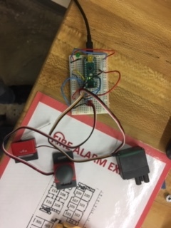
I am currently in an engineering design and development class. In this class we got to choose a project that we were going to do and my group chose to do a lock that will automatically lock a door. We have decided to use an arduino nano for this project. The mechanism locks after 6 seconds of a limit switch being held down and it is supposed to unlock if you push another button. The mechanism locks the door perfectly fine after the 6 seconds but after it locks it will just randomly unlock instead of unlocking when you push the button. Below are a picture of the aruino nano on the breadboard and the code. Please help.
#include <Servo.h>
const int limitSwitch = 3;
const int ledPin = 13;
const int servoPin = 7;
const int unlockPin = 2;
int light = 0;
int setting = 0;
int yes = 0;
int pos = 90;
Servo servo;
void setup() {
// put your setup code here, to run once:
pinMode(ledPin, OUTPUT);
servo.attach(servoPin);
pinMode(limitSwitch, INPUT);
servo.write(pos);
}
void loop()
{
while(setting == 0)
{
while(digitalRead(limitSwitch) == LOW)
{
light = 1;
if(yes == 48)
{
pos = 160;
servo.write(pos);
}
if(light == 1)
{
digitalWrite(ledPin, HIGH);
}
if(light == 0)
{
digitalWrite(ledPin, LOW);
}
delay (125);
yes += 1;
while(yes > 48)
{
if(digitalRead(unlockPin) == HIGH)
{
pos = 90;
servo.write(pos);
yes = 0;
}
}
}
if(digitalRead(limitSwitch) == HIGH)
{
light = 0;
delay(20);
}
if(light == 1)
{
digitalWrite(ledPin, HIGH);
}
if(light == 0)
{
digitalWrite(ledPin, LOW);
}
digitalWrite(limitSwitch, HIGH);
}
}