I am currently in the process of making a hacked billy bass. I am using the following tutorial:
The part that is confusing is about getting the audio sound levels as an input.
In this tutorial the maker just hooks up the audio jack to the analog input port.
I have done some research. Instead of making it clearer, it got more confusing.
From this thread I understand you should not hook the audio jack directly to the anolog pin of the arduino.
Note that I am a complete newbie to electronics, instead of just following instructions I like to understand what I am doing.
In the thread the following schematic was posted:
I am unable to comprehend what that circuit does and how it functions.
Things I do not understand/basic electronic lessons needed:
What is the capacitor used for. A simple google search tells me a capacitor stores energy and then quickly discharges it.
Wikipedia:
A capacitor (also called condenser, which is the older term) is an electronic device that stores electric energy. It is similar to a battery, but can be smaller, lightweight and a capacitor charges or discharges much quicker. Capacitors are used in many electronic devices today
I don't see what the function of that could be in this schematic.
Why does the A0 pin has to be connected to the 5V pin? (with a resistor) It is some sort of voltage divider.
When there is no input from the audio source. The voltage to A0 will be halved: So it will be 2.5V at rest.
What happens when there is coming input from the audio source?
How will that interact with the signal to A0?
I assume when there is no incoming signal: Current on A0 will be 2.5v -> A0 input will read 512.
I read that such a audio jack produces an AC Current. To measure how loud the sound is should I take the absolute value of 512 - [actual input from A0 pin]?
What voltage range does the audio input produces. I am planning to hook it up to my phone or laptop. Does this range differ per audio source or is it always within a specific range?
I will probably use the NodeMCU(esp8266) instead of Arduino. The key difference (I think) is that it uses 3.3V instead of 5v. Does this matter for the schematic. If I use the same voltage divider: The input at rest will become 1.15V right? So it is still half. So I can use the same schematic for this right?
If it is not possible with a nodemcu I will purchase an Arduino
Thank you for your reply. I am a software developer so my programming skills are ok.
I have always had an interest in the hardware side of things. I have played a bit with a raspberry pi, and recently purchased some Esp chips.
I have never really made complicated circuits.I have just plug some sensors/buttons in.
The only knowledge I have regarding electronics is from Highschool Physics class. Which is not much I am afraid.
The difference (how I perceive it, I could be wrong) between the 'sensor' I am trying to build now and the one I used is that the other sensors were 'powered' by the ESP/Raspberry pi. Thus the voltage is always between suitable ranges of the RaspberryPi/ESP. (Input of the sensor is also the max voltage out.)
I am unable to comprehend what that circuit does and how it functions....
...Why does the A0 pin has to be connected to the 5V pin? (with a resistor) It is some sort of voltage divider.
When there is no input from the audio source. The voltage to A0 will be halved: So it will be 2.5V at rest.
What happens when there is coming input from the audio source?
How will that interact with the signal to A0?
I assume when there is no incoming signal: Current on A0 will be 2.5v -> A0 input will read 512.
I read that such a audio jack produces an AC Current. To measure how loud the sound is should I take the absolute value of 512 - [actual input from A0 pin]?
Right!!!
Audio signals are AC. They swing positive & negative. The Arduino can't read negative voltages. In fact it can be damaged by negative voltages (or voltages greater than +5V) and/or the audio signal can be "damaged" (distorted).
With the voltage divider in place, the DC voltage is added to the audio signal. With low level/quiet signals you'll get ADC readings that "swing' slightly above and below 512 and high/loud signals can read between 0 and 1023. You can subtract the bias out of the reading in software if it helps in your application.
What is the capacitor used for.
A series capacitor "blocks" DC, but allows AC through. The capacitor along with the resistors form a [u]high-pass filter[/u]. Since DC is zero Hz, it gets blocked. (If the capacitor value is too low, it will also block the bass, etc.)
Without the capacitor, the connected device could potentially mess-up the 2.5V bias and/or the DC bias could get-into the connected device and cause unknown/undefined problems.
MikeLittle:
You have 2 INPUTs tied together. Where is the audio OUT?
The audio output will come from an external source. Which will be used as an input for the arduino. The Arduino will not have an Audio Out. (The plan is to use a splitter to send the audio to a speaker.
DVDdoug:
With the voltage divider in place, the DC voltage is added to the audio signal. With low level/quiet signals you'll get ADC readings that "swing' slightly above and below 512 and high/loud signals can read between 0 and 1023. You can subtract the bias out of the reading in software if it helps in your application.
That is a neat trick. One thing that I am missing is that there is no protection for when the current from the audio source is to big. In theory when the volume is high enough it might still reach >5V?
Or will this value never be reached? (Because of guidelines for audio output devices perhaps?)
DVDdoug:
A series capacitor "blocks" DC, but allows AC through. The capacitor along with the resistors form a high-pass filter. Since DC is zero Hz, it gets blocked. (If the capacitor value is too low, it will also block the bass, etc.)
Without the capacitor, the connected device could potentially mess-up the 2.5V bias and/or the DC bias could get-into the connected device and cause unknown/undefined problems.
Thank you for the explanation, tomorrow after work I will look for more information about capacitors and their uses. (And try to understand the math and behaviours behind it.)
I came across another schematic as a possible solution for what I am trying to do. I will try to understand that schematic myself first (and then probably post it here to check if my understanding of it is correct).
In theory when the volume is high enough it might still reach >5V?
It is unlikely from an audio jack.
However that circuit will not help you find the audio sound levels as an input, it will allow you to read in the audio waveform.
You must learn that most Instructables electronics articles are crap, written by people who think they know more than they do. What you need to do this is a peak envelope detector circuit. Like this one:- Envelope detector - Wikipedia
Though you can do the peak detection in software of course, if you are sampling the input
waveform. Minor quibble - that circuit lacks any over-voltage protection - adding 10k between
the voltage divider and the analog pin will make it pretty-bomb-proof. Make R1 100k, R2 10k,
C can be around 1uF - if its polarised the negative goes to the audio input jack.
Adding an opamp for hardware peak detection increases the hardware complexity, software
approach avoids that.
Minor quibble - that circuit lacks any over-voltage protection
But you are not likely to get over 5V peak from an audio jack. You also have the forward volts drop of the diode and the capacitor to absorb brief spikes.
A 10K series resistor will reduce the attack speed of the detector and make it a lot more sluggish in its response.
Thanks for your input. As Grumpy Mike suggests, I should make an envelope detector.
I thought I would use the schematic posted here.
I am running into a question.
What kind of capacitor should I use? I see different kinds: Ceramic, aluminum, .....
Does it matter which one I buy? As long as I have the right value? 10uf?
Grumpy_Mike:
But you are not likely to get over 5V peak from an audio jack. You also have the forward volts drop of the diode and the capacitor to absorb brief spikes.
A 10K series resistor will reduce the attack speed of the detector and make it a lot more sluggish in its response.
I'm thinking nylon carpets and static for the source of spikes really, and the 10k on the analog pin doesn't
affect the attack speed surely?
Been a while as I did not have time to play with this project. Yesterday evening I fiddled a bit with the project.
I tried to make the envelope follower linked to by Grumpy Mike. Unfortunatly it did not seem to work.
(I have probably attached something wrong.)
I used a potentio meter for the Resistor, to dynamicly change it. Put a diode on it and a 2.2Uf capacitor, as well a 10uf capacitor.
I got no inputreadings on the A0 pin whatsoever.
I still don't understand how the schematic works. Where in the schematic should I measure the voltage (i.e. connect to A0). As I think I might have that wrong.
I did try the other schematic I posted (This one). I realise this schematic is bad, and it can damage the arduino. (So anyone reading this, don't try this..)
I was able to get the desired effect. (Although it is very jumpy.)
When inserting a diode to this schematic (between the potentiometer and the Capacitor) I can't detect a signal anymore.
(I am pretty sure I inserted the Diode the correct way(Such that the positive current can flow though it.)
Any ideas on what I am doing wrong?
My 'ideal' solution is to use the Envelope Follower provided by Grumpy Mike. Can it be that I used an incorrect Capacitor what value of Capacitor would you guys suggest? Also, does any diode work? On the packaging of the diode I am using it sais: 1N4001
Grumpy_Mike:
Not without you posting a good picture of your wiring.
That is a rectifier diode and while it will work the response is not so fast, so try a small signal diode like a 1N4148.
Also with a diode your audio signal needs to be above 0.7V for the diode to conduct.
Thank you Mike.
I understand it is dificult to give an answer without a picture of the wiring. (It is also hard to produce a clear picture of the wiring.)
I will probably drive to the store to get the 1N4148. And see if that works. If it fails I will take another attempt at making a clear picture.
Does the signal also has to be above 0.7V for the 1N4148?
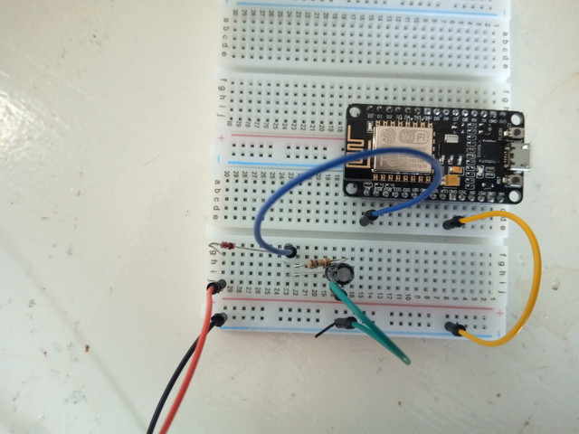
I did not have the right colours jumper wires laying around, so this will have to do.
The blue wire is connected to A0 of the nodemcu, the yellow wire is connected to the ground.
With very load volumes I am getting a reading, otherwise I get no reading at all.
Can this be due to the fact that the diode only conducts when the voltage is above 0.7V?
Is there another Diode I can try whos forward voltage drop is lower?
Or should I find a way to amplify the signal?
With very load volumes I am getting a reading, otherwise I get no reading at all.
Well that shows something is working at least.
Try dropping that capacitor to 22nF or so and see if it improves.
Can this be due to the fact that the diode only conducts when the voltage is above 0.7V?
It can in part but with such a small signal it is not going to be much good if you get a lower forward volts drop diode. You could either use a Schottky diode or a germanium diode but the volts drop is still in the order of 0.2V.
Or should I find a way to amplify the signal?
Yes, look at getting an op-amp that you can run off 3V3 so you don’t have to worry about sending too much voltage to the processor.